The kxmx_bluemchen - An open source, 4hp, Daisy based Eurorack module

Hi Everyone,

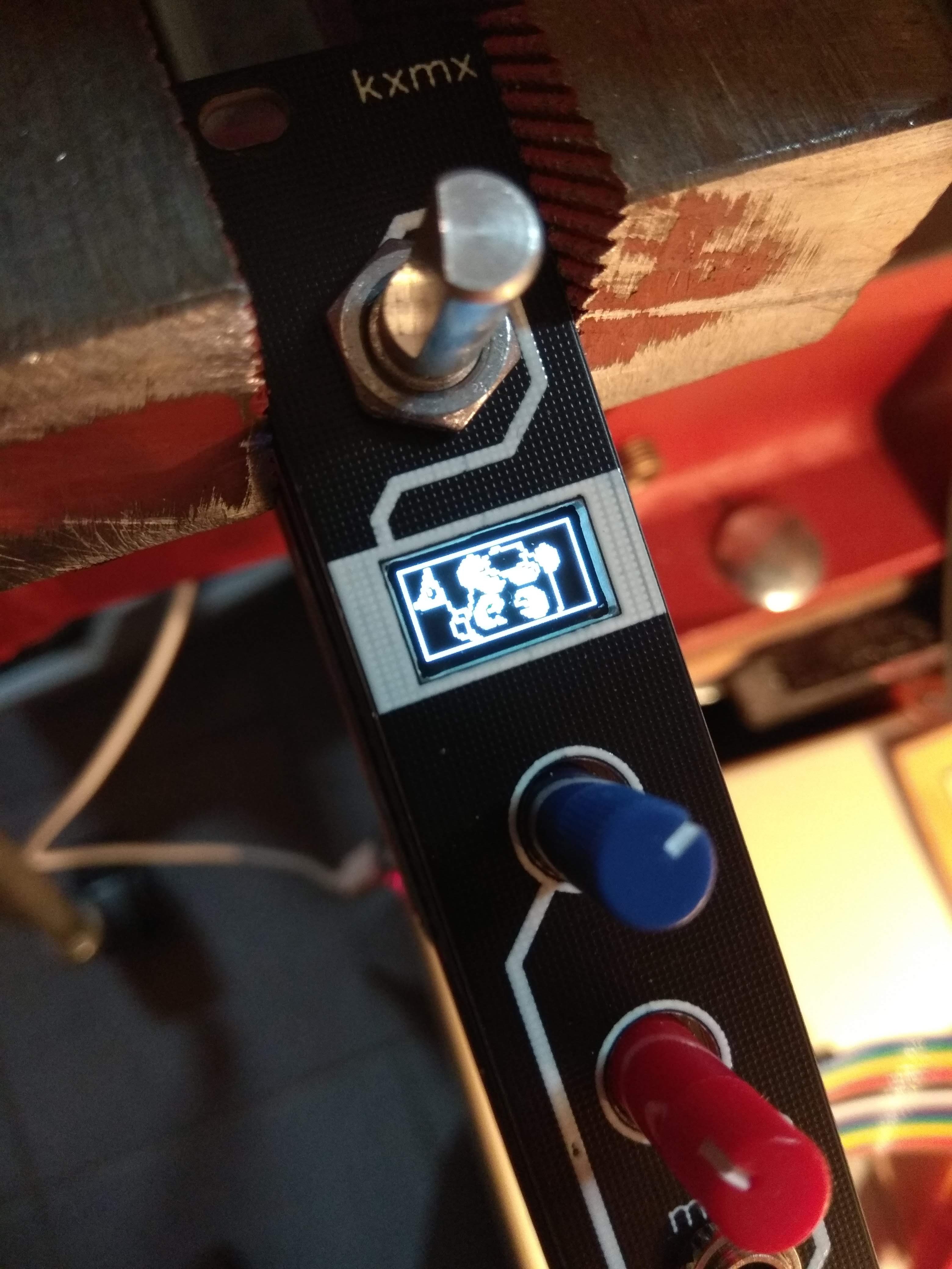
I’d like to share with you a little project I’ve been working on in my spare time. It’s an open-source, Daisy based Eurorack module in only 4hp. It’s called the kxmx “bluemchen” (little flower in German) and looks like this:

It’s basically a Patch with fewer controls. Heres what it does have:

1 Rotary encoder with switch
1 64x32 OLED display
2 Potentiometers
1 MIDI in
2 CV in
2 Audio in
2 Audio out

I needed two PCBs to accommodate the components. I ended using 20 pin stacking headers to get some of the Daisy signals from front to back. I used 0603 SMT parts and it’s hand solderable. Here’s what it looks like from the side/back:

I’ve tested most of it from a hardware design perspective. The encoder, CV, Audio, MIDI all work in the prototype. I’ve successfully flashed some of the example patch firmware.

I haven’t tried getting the OLED going, as the patch version is SPI, and this little one only comes with I2C signals (I’m not entirely convinced a screen is a good idea anyway).

The prototype is prone to the same digital noise problems a few people here have mentioned. I’ve since the revised the power supply to more reflect the design of the Patch, but it’s not yet been tested.

On the software side of things, I’ve done nothing but test basic functionality. I’ll try and address this when the new power design has been prototyped and tested.

As mentioned this is an open source design. Here’s the back board:

…and the front board:

…and a front panel:

I hand picked the components from LCSC and prioritized parts that have PCBA support and high stock counts where possible. With the exception of the Daisy, OLED, and the Jacks, you should be able to order the entire BOM in one go.

I’ve been sitting on this prototype for a while, unable to find the time/motivation to move things forward. I figure if I just put it out there, and there is interest, perhaps it will get things going again. I’d appreciate any kind of feedback!

13 Likes

This looks awesome. Maybe remaining unused pins could be exposed as an expander header?

2 Likes

Did you solder this yourself ? I thought JLCPCB could only assemble SMT components on green PCBs ?

1 Like

Definitely. I like how a lot of Instruo modules ship with a 1u expander to provide additional CV control. There is quite a bit of free space in the middle of the back board for something like 50 mil pitch headers, but getting the signals down there on a 2 layer board would be a challenge.

I did, it took about 3 hours.

I’ve never tried the JLCPCB assembly service, nor do I know their restrictions/requirements. I simply picked parts from LCSC that are listed as PCBA basic or extended. I know a lot of DIYers aren’t keen on SMT soldering, but it’s necessary for this form factor. Just trying to keep it accessible.

Ah ok, good idea for those of us with declining eyesight :slight_smile:

I really like your accessibility approach, but with this design it doesn’t worked out.
But it’s nothing dramatic, I think your design only clashes with the Terms in it’s Size 18mm < 20mm

JLCPCB PCBA restrictions:
Only below PCB Specs are available for SMT assembly service.
If you want us proceed your order including assembly, please re-select the PCB Specification.

· 2-layer PCB(Qty≤30pcs)
· 4-layer PCB(Qty≤30pcs)
· 2&4 layer PCB
· Min. PCB dimension 20x20mm
· 1.0/1.2/1.6mm board thickness
· Green solder mask
· 1oz copper weight
· Only Tab Routing Panelization is accepted.
Note: “Panel By JLCPCB” option is not supported.

Only accept single sided placement, we recommend you choose the side which has more SMD parts.
The parts that are not in JLCPCB SMT Parts Library won’t be placed on your board.
The order panelized by v-cut can not be made with SMT assembly.

1 Like

Would be nice if someone orders a batch of PCBs and make them available here for purchase, or even a kit (PCB with BOM parts)

1 Like

Ok I just changed the size to 20mm, and was able to get through.
It seemed that the Orientation on some Parts was wrong, but I think it’s due to substituted Parts.
For 10 SMT assembled Back PCBs it would cost about 60€ + 20€ for shipping to Germany incl prepaid Tax.
The other Front and Panel PCBs could be thrown onto the same Gerber to save a few bucks. But not sure if it’s worth the hassle with cutting and sanding for that little Money. The Real advantage would be, that the size of the Board, could stay at ~18mm.
The funny Thing is, that I don’t even order it. Was just curios if easyEDA can really simplify the ordering process =) but the steps with exporting BOM and PnP, just to upload it a few sec later seems little awkward to me.
Your other Project Klangkarte, looks also pretty interesting. Wanted to build exactly this since Paul released the TDM Support for Teensy 3.6, but I’m little afraid of SMT soldering and LCSC doesn’t have the CS42448.

@shensley does Daisy actually support TDM on SAI2? If yes how much of an effort would it be to port the CS42448 driver from Teensy?

@recursinging I’ve just noticed that bezel on the OLED which makes it look a nicer fit on the front panel. Could you say where you got it from ?

Hi all, thanks for the feedback,

No bezel, just a cutout in the PCB, The white you see is just silkscreen on black soldermask.

Thanks for giving the PCBA service a try. I wasn’t aware of the size restrictions, and I haven’t considered how best to panelize the design. I’m sure there are a number of design decisions that I made which will need to be re-evaluated in the context of a PCBA service. It seems you were just getting an idea of the PCBA pricing, but be aware, as I mentioned earlier, I had problems with digital noise and since redesigned the power management section. It has not yet been fabbed or tested, so please consider the design a prototype at the moment. I’d suggest just ordering the boards, and BOM, and have a go at hand soldering.

Don’t be. Get a halfway decent Iron with a fine tip, some tweezers, some flux, some leaded solder (while you still can) and go watch a few youtube videos. It’s a lot easier than you think.

Honestly, for bare PCBs, it’d be cheapest to simply order them from JLCPCB (via the project in EasyEDA), or export the gerbers and use your fab house of choice. If there is enough interest to warrant it, I could invest some time in learning the ins and outs of the PCBA service, and put together kit. It would be prudent though, to first ensure the design is mature enough. That might take time.

1 Like

like @everNoob, I’ve also had a go at getting a quote for PCBA service from JLCPCB. There are a few things to be done, but they are do-able. Before I order a run though, I’d like to finalize the design, and do one more prototype run for testing. For that I’d like to pose a couple of questions to those interested in a module like this:

  • MIDI - Does anyone see a strong use case for MIDI in? It opens up the possiblilty of parameterization beyond the front panel, but doesn’t fit well to the modular ethos of “do one thing and do it well” There would be space for two more CV inputs, or the two DAC outputs if I were to get rid of it…
  • OLED Display - I don’t like menu-diving, and swiss-army modules require mental gymnastics to operate (I’m looking at you Disting…). But the goal of this module, similar to the Patch, is not to fulfill a specific function, but to allow for experimentation (or for myself specifically, to better learn DSP). In this context a little bit of feedback can be invaluable, plus the .49" display fits so conveniently, I tend towards keeping it.
  • SD-Card slot - I think I might be able to fit an vertical SD card slot into the design. This opens up a pretty wide range of possibilities, but also smells a bit like feature creep.

Please feel free to give your opinions, I hope to get a new prototype fabricated by the end of the week.

CV is more important than MIDI on a eurorack module. It makes more sense to add MIDI IO with an expander for a module of this size.

1 Like

MIDI - yes. MIDI changed music generation, why go back to the 70s ?
OLED - yes.
SD-card - not on the front panel. But would be nice to be able to reprogram the Daisy from the front panel. Problem is you need the reset and boot pins as well as the USB or UART pins, which gets complicated.

MIDI yes, OLED yes, SD-card yes, it makes it more compatible with Patch, so you can have granular synth, sample players, recorders etc.

After trying and testing a few thing, I made some decisions.

  1. MIDI in stays, although I might drop the bridge-rectifier and just stick with one of the two TRS variants like every other module, there are adapters for this.
  2. MicroSD is being added to the front panel. There is just enough space for it, and the position makes for nice short traces and easy routing.
  3. OLED stays. I got it working, and I find it looks pretty cool and will probably be quite useful.

While I can appreciate the wish for bringing the USB port to the panel, this is just too complicated. Anyhow, I see the USB firmware upload mechanism for folks who aren’t developing, but flashing pre-compiled firmware, and probably not too often. Anyone who is actually developing firmware will want access to the debug pins.

Now the features are set, I’ll try and finalize a hardware design and order a final prototype soon.

8 Likes

Heya! First off, woah! What a cool project; looks great!

Looking at the TDM format as shown in the Datasheet, it looks like this would be totally possible. Depending on the Peripheral architecture of the teensy, it may not be trivial to port the driver, but SAI2 can be configured for 8 slots of 32 bits (256 bits total per frame) for each channel. The limitation being that it can be a maximum of 256 bits in a frame.

Setting up that configuration shouldn’t be too hard, and then it looks like either SPI or I2C can be used to control the codec.

1 Like

This project is very exciting, that’s exactly what I was looking for or considering to make. The form factor (and being a kit) are much better than a Patch to me.

My current attempt was to get a Radio Music PCB + Panel kit just to use the front board on top of the Daisy Seed. It works well for the audio out (but only mono) and the knobs, but then things get more complicated about the switch (pulldown design, works but noisy) and the analog vs. digital 3V3 confusion, not even talking about the CV inputs…

About the bluemchen, ideally I’d love to be able to repurpose the audio IN into CV IN when needed (a jumper somewhere for the DC coupling?)

If/when anyone wants to share a PCB/BOM/SMT assembly batch I’m in for a few units :grinning:

I was also hoping to make this possible, but it is not due to a design decision Electrosmith made with the seed. The codec they used has a digital high pass filter on the ADC side which cannot be disabled in software. I made mention of this a while back here:

I’m currently waiting on my second revision PCBs to be delivered. I hope to populate and test this revision in the coming weeks. If all goes well, I plan to offer a few DIY kits with parts and through-hole only soldering soon after. I’ll be updating this thread with my progress, so stay tuned if you’re interested.

1 Like

Great, I’ll wait!

On the DC coupling thing, perhaps the ability to re-route the audio IN signal conditioning to ADC of the Seed via jumpers would make some sense to offer more modulations for synth-ish applications (no need for extreme accuracy). But even without that the project is very appealing for sure.

One potential solution is to buffer the Audio input, and split it to a bipolar->unipolar CV circuit, and to the audio input circuit.

This would allow you to read it as DC-blocked CV or as audio, but would require a few extra op-amp channels.