Not sure I understand your suggestion - maybe a schematic. But anyway if people want to read DC signals with the audio ADC, one possibility is to set up a free running timer on a GPIO and drive a chopper transistor. Google for “chopper stabilised op-amp” from back in the days when a 741 was state of the art and you’ll find all the theory on this.
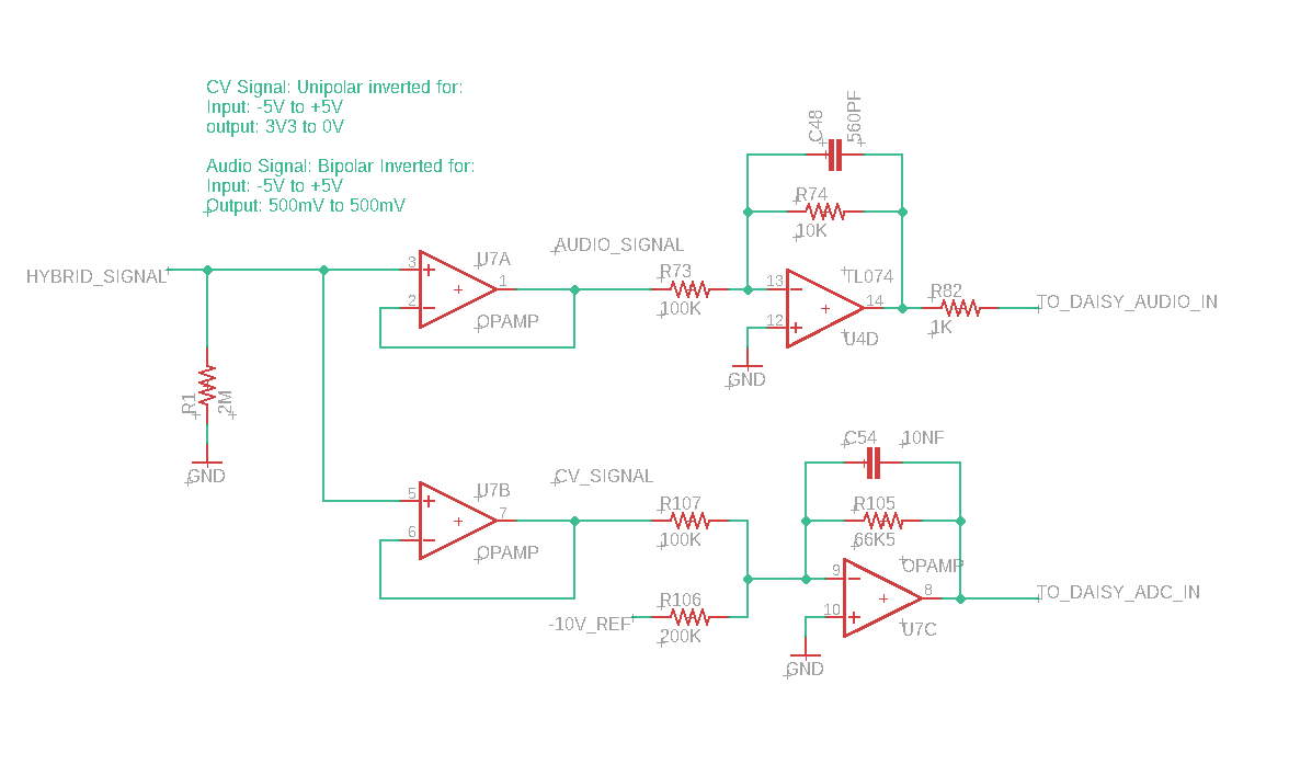
Something along these lines, is what I was suggesting. This is just copy/paste from the Daisy Patch sch, but buffers the input before going to each destination amplifier.
Fascinating about the chopper transistor. A lot of interesting stuff to read on that.
EDIT
It was pointed out to me that the output says 500mV to 500mV – this is a typo, and should read “500mV to -500mV”. Apologies for any confusion.
Is that comment in the schematic correct? Audio signal output is 500mV to 500mV?
The +/-500mV (aka 1Vpp) is from a 10Vpp signal. The AK4556 clips at about 2.1Vpp, so this allows for about 6dB of headroom. That covers pretty much anything within the Eurorack rails, minus diode drop, etc. (about 20Vpp)
The schematic says 500mV to 500mV, which doesn’t make sense. It’s a typo, but should be corrected.
There are some interesting ideas here for getting DC and low frequency signals into the digital realm, but they seem (to me) to make compromises in order to get there.
This seems like a good idea for DC and low frequency signals, but would it not limit the upper bounds of the usable bandwidth to half of the chopper frequency? Additionally the chopper frequency would theoretically be limited to at most, half the codec sample rate, right? If I understand correctly, this means you’d need to disable the chopper in order to use the codec channel for audio purposes.
Indeed, this allows you to sample the signal at frequencies down to DC using the ADC of the STM32. In a space constrained design, this is interesting as it essentially allows for the re-purposing, or even simultaneous use of an input jack in software. But you’d also have an upper bound on the usable bandwidth unless you sampled the ADC of the STM32 at the same sample rate as the audio codec.
Both of these ideas though, require treating DC/low frequency signals different than higher frequency (lets say >10hz) signals in software. In the analog realm of modular synths, this distinction is not nearly as strict. I’d find it more intuitive to have access to codes at DC, low frequency, and high frequency inside of the AudioCallback at the audio sample rate. I think that would make for some creative modulation possibilities.
All of this is only really relevant when dealing with a “platform” type module like the Patch or the kxmx_bluemchen (or the Disting, o_C, etc.), where the hardware defines the constraints of the software you flash to it. Otherwise, you’d typically design for your goal function anyhow, turning these kinds of compromises into decisions.
Specifically to the kxmx_bluemchen, I’m not considering any of the above mentioned workarounds. If a future revision of the Seed supports reading DC/LF signals with the codec, that’s cool, otherwise it’s just another constraint to consider when writing the software you’d like to flash to it.
@recursinging : yes that’s a correct understanding of using a chopper. But as it’s software controlled, just stop the chopper if you want full bandwidth audio to pass through. I can’t think of any signal that is full audio bandwidth and needs a DC component - in fact DC is what you need to get rid of in most audio signals. Modulation frequencies tend to be less than a kHz or two at most, usually far lower.
I’d also not support changing the Daisy Seed as once you enable DC into audio ADCs you often get all sorts of biasing problems, which will cause more hassle than it solves for less experienced users. This is why the defaults on audio ADCs are usually HPF enabled.
@MikeDB In my very limited understanding, a FM Input would require DC and Full Audio Rate or do I misunderstood something?
Surely it requires DC or full audio bandwidth. For CV operation you obviously need DC, but the Daisy does have several ADC inputs which can sample at 16 bits/3.6Msps so no problems there.
For FM synthesis you could use the ADCs with some additional circuitry, but it is probably easier to use the audio input. But if the modulation signal has a DC offset then the carrier oscillator will be offset from the proper frequency and so the results will not be harmonically related. But if this is what you want then the same effect can be simulated by adding a DC input on an ADC (or a software constant) to the audio ADC.
In any case for normal operation we need to ensure the modulation and carrier are harmonically related, so they really should both be generated on the Daisy so they are using the same clock, otherwise the results are going to be a bit unpredictable.
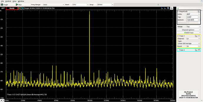
So, I got the rev-2 boards mostly soldered up (those vertical microsd sockets don’t seem to exist outside of Thonk), plugged it in, only to hear this:
To the left and right of the pilot tone you might notice the dozens of noisy little spikes, each one poking a little hole in my ego, and letting my motivation drip out the bottom.
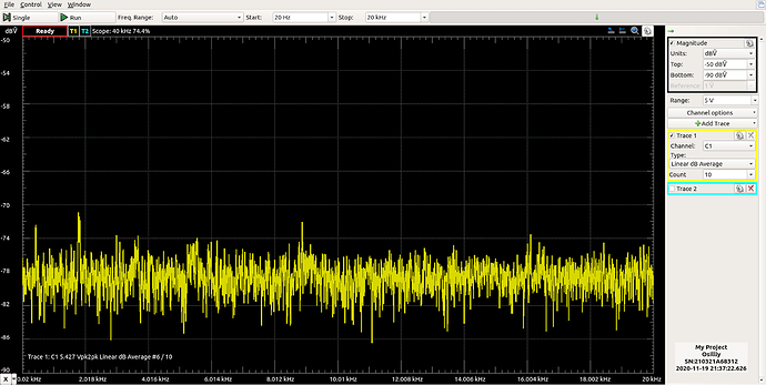
I spent a few hours isolating things to track the problem down. I’ll spare you the gory details and just share my solution; I soldered a 24 gauge wire between the Seed AGND, DGND pins, and the Eurorack Power GND pins. This is what I got:
Notice the scale of the graph… Blissful silence (well almost).
OK, so I kinda sorta suspected this might bite me in the ass. In order to keep the back PCB at two layers, I had to route the GND (AGND & DGND) nets around the board using traces, as the routing is far too dense for any substantial contiguous copper areas. Sadly, it seems that workaround just won’t cut it for the Daisy.
I see two possible solutions to this problem:
- Change the back PCB to a four layer design with proper GND planes.
- Re-design the front PCB (which is much less dense) to have generous, contiguous GND copper areas, which should effectively do the same job as the jumper wire currently.
#2 is the most economical solution. Four layer boards cost about 5x as much a two layer boards, even if they are now cheap enough to not be considered a barrier of entry. Relying on the front PCB also means the back PCB can’t effectively be used without it, something nobody outside myself probably cares about.
In conclusion, it’s getting there, but I’ll need to do another revision to get this sorted out.
Thanks for sharing the progress, it is progress indeed! You didn’t ask, but just in case I’d believe option #2 is worth exploring.
It is, but it might be a dead end. I’m not sure how to quantitatively determine whether or not the disparities in potential between points in the current GND network of traces (what I assume is the problem) would be relieved by a copper area joining the through hole junctions above it. But, I guess that’s exactly what the jumper I soldered in does.
A network analysis of the analog audio circuitry without the Seed showed a -90dB noise floor, so that part of the design is fine. Quieting the ripple of the Seed’s DC-DC power supply with additional filtering did nothing. Only in conjunction with the effects of the Seed’s STM32 on the ground traces do the noise problems arise. That’s why I suspected the Seed AGND, DGND and Eurorack power GND nets need a lower impedance path to each-other. Copper areas on the top board should be able to provide this, I guess.
It’d just be unfortunate if I go through the process of making another revision only to find that option #2 doesn’t solve the problem.
Just go with 4 layers. Even if you can solve it on 2 layers, I bet it will be better on 4.
Assuming you are ordering from a Chinese supplier such as JLCPCB the price differential has reduced considerably in recent years. Indeed I think they do 5 off prototypes at a similar cost to 2 layers.
Is this module available anywhere as a built item ??
I have two prototypes from earlier revisions in my workshop that I’d be willing to part with if you are interested.
Otherwise you’ll have to wait. I’ve made significant changes to the last revision which I’ve not yet had fabricated, nor tested. My goal is to make a small number of DIY kits and built modules available for purchase, but I want to make absolutely sure the design is solid. Unfortunately my progress on this front has slowed significantly since the Kindergarten closed here in mid Dec.
I’ll be updating this thread whenever I make any significant progress.
Definitely interested in a no-screen smaller size Daisy euro DIY module!
Same here, I’d be very interested as well 
I like the design very much. Could you provide some details what is required to get the OLED working?
I just hacked the libDaisy OledDisplay class to use I2C instead of SPI, and changed the initialization routine to reflect what the SSD1306 expects. The rest of the libDaisy graphics driver works as expected. I’m waiting on some updates to libDaisy to make an actual integration possible. Until then I don’t plan on trying to re-invent the wheel.
In other news, I’ve made some progress.
I decided to revise the 2 layer design to address the grounding problems I mentioned above. I had rev3 fabbed and soldered one up yesterday… and it’s nice and quiet.
Also, the changes I made to the MicroSD routing seem to have helped quite a bit as now I’m able to run the new libDaisy defaults despite the GPIO drive strength/slew rate at GPIO_SPEED_FREQ_VERY_HIGH. So, fast MicroSD access is possible.
The MIDI rectifier circuit has been replaced with a set of jumpers for switching between TRS-A and B. I also removed the over-current protection. I also added additional bulk capacitance to the power supply circuit and generally optimized the BOM for PCBA.
I’m going to do a few more tests on this revision. If all goes well, I’ll give the PCBA service a try, and should then be able to make DIY kits, or built modules generally available. Also, I now feel confident the design is solid. Should anyone want to try and make their own, just get in touch, and I can help sourcing some of the parts.
Otherwise, for those who are genuinely interested in obtaining a built module or a kit, please let me know.
Wow, great news! I am very interested in a kit. Or even a couple. Greetings from Hamburg.


