Here’s a small project I’ve started recently. To @recursinging’s recommendation, I’m posting it here
So, it started out as a mod for the amazing kxmx_bluemchen/kxmx_nehcmeulb module to add more knobs but drove me into expanding it more.
Margarita Prototype is originally a rework of the kxmx_bluemchen and kxmx_nehcmeulb. Based on a Daisy Seed.
It accommodates 7 knobs with CV attenuation, 2 gates-in and the original features, except the OLED screen and the push encoder which will feature on the expander alongside more knobs and CV with attenuation and some more. Speaks Eurorack. UNTESTED.
Motivations: learning electronics and MCU programming so i can make weird music.
Making this stuff affordable; I’m trying to use JLCPCB’s Basic Parts when possible (of course, that doesn’t include ICs) to maintain the price to a minium.
This is a work in progress. It started out as a quick mod from kxmx’s design but it triggered a cascade of ideas that will have me squeeze the nectar out of the Daisy Seed to get basically as many controls and ins and outs as possible from this cute little board.
This version doesn’t have yet any headers for the expander but I plan on replacing the 7th knob (ADC11) with a header linked to a muxed array of knobs.
This is my first ever PCB design but I’ve already learning quite a lot in the process. I’m open to any criticism and ideas regarding layout, features, PCB design, etc, etc… BTW I didn’t manage to find stackable female headers 3D model and part on easyEDA so it’s just warned in all caps on the schematics until I figure that out.
Expander: so I’ve been planning the expander to have several knobs via a multiplexer as mentioned above but I’m also interested in getting a PCM3060 codec, divide its clock and get many i/o (ie: 2 outs at 192kHz would give 8 outs at 48kHz, in theory).
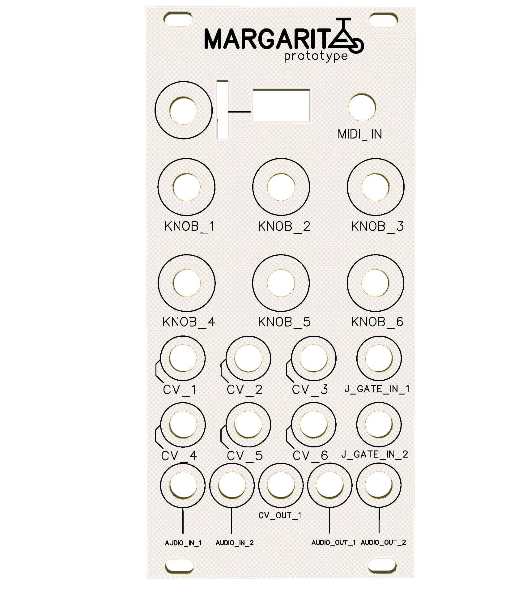
I haven’t done the panel yet. But it’ll be done soon-ish. It’s meant to be 12HP.
Firmware-wise, I’ll wait til I receive and test it. Hopefully this will evolve into a solid prototyping platform!
Kudos to @recursinging for the inspiration, motivation and the beautiful open source modules!
If I may offer a couple of quick suggestions, since your are early in the development process…
Try and get everything onto a single PCB. At 12hp you almost certainly have enough space. It might be a bit challenging to place and route around the knobs and jacks, but the effort will be worth it.
The price of 4 layer fabrication is so low, it’s almost a no-brainer to take that route. The non-contiguous GND/AGND copper areas you have now will create noise problems. Save yourself the hassle and switch to a four layer design with a dedicated GND/AGND layer.
Consider including a couple of LEDs or some other form of visual feedback in the design. This becomes very useful when you start developing firmware. Early in my design process I considered ditching the OLED, but boy-howdy, am I glad I didn’t. I use it constantly.
All in all, I’d say you’re off to a good start. I learned most of what I know about PCB design while developing the kxmx_bluemchen. It’s a rewarding challenge, but the feedback loop is much larger and more expensive than when developing software. It’s worth it to take your time and ask questions.
I’ll definitely take your suggestions; I wasn’t aware of the possible noise issues.
Very good point about the OLED/visual feedback. I’ve actually already planned a overhaul:
muxing will need 4 ADCs (basically the Field configuration), so I need to rebalance the number of knobs+cv, cv out and gate ins. The OLED is coming back and so is the encoder… I think!
If I put all SMD on one side and all THT on another it should work I reckon, I’ll give that a go. There’s lots
of free space asking to get crammed.
Anyway, appreciate your feedback!
Firmware-wise, I want to implement NRPN/14-bit MIDI although I haven’t researched anything yet so I don’t know if that’s possible on the Daisy or how (but I assume it’s doable, logically).
Have updated the project! Soooo…
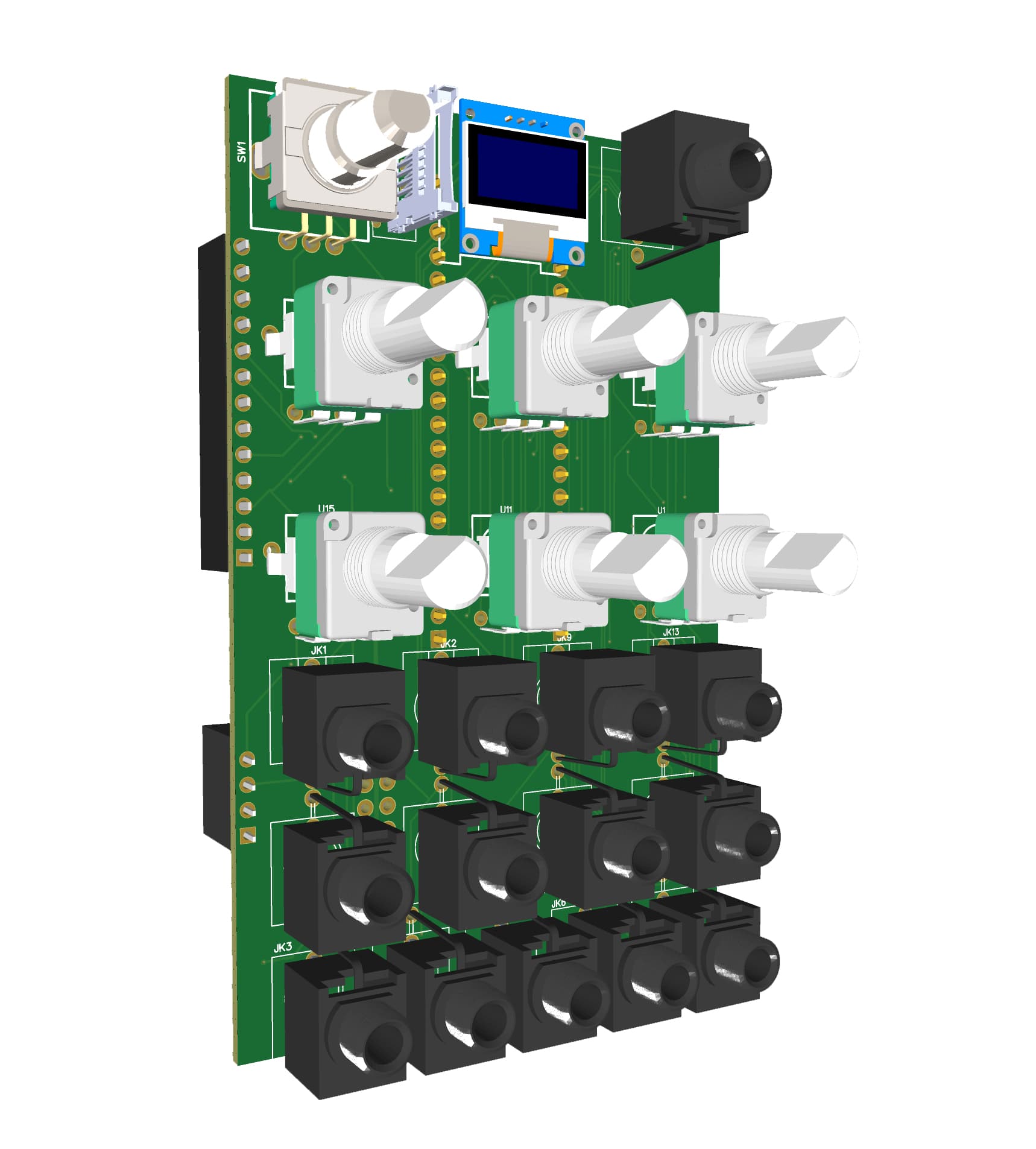
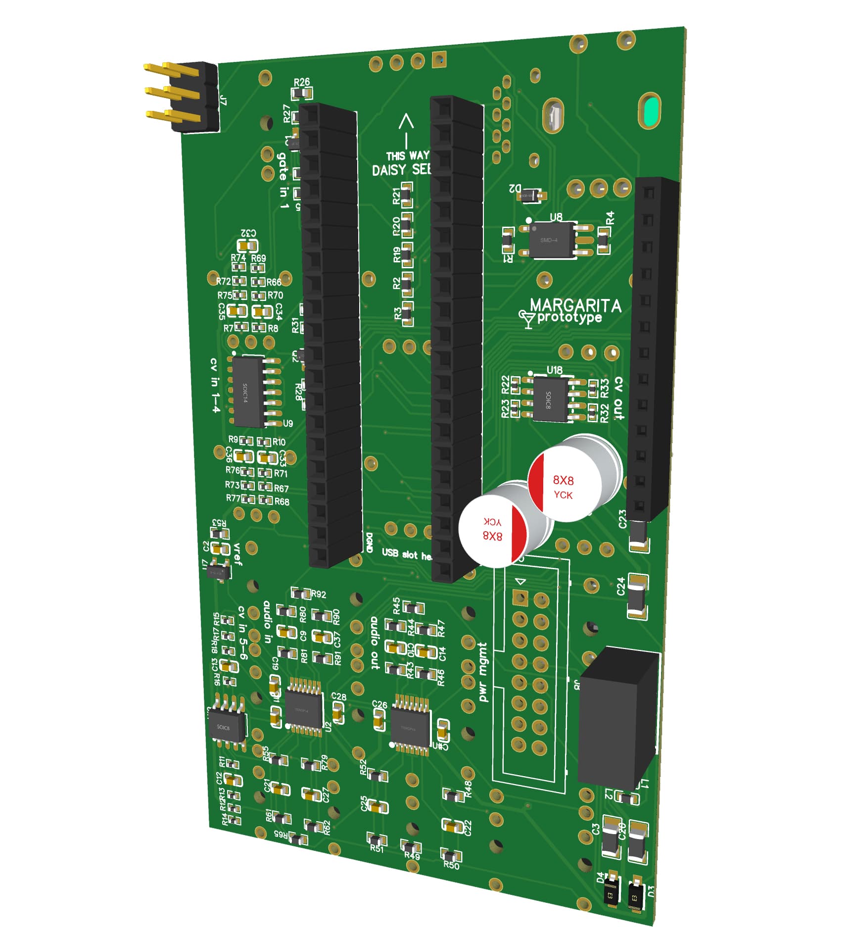
It’s a single PCB now, has individual GND and +3V3A planes, managed to fit 6 knobs with CV, 2 audio ins, 2 audio outs, 1 CV out, MIDI in, 2 gate inputs and the OLED and rotary encoder are back!
VCC, VEE and VREF tracks need to be thicker and will work on an alternative wiring this weekend as well as a 12HP panel. Then I can finally order and test it.
I’ve added a female header for the expander but it’s meant to change… It carries the SAI (i want to use it for audio expansion), SPI1 (usage TBD) and USART1 TX (probably for MIDI out…)
I’d like to find a linking solution with less real estate… I know there are a few like HDMI (used in Links) which has been debated here and here… There are some good arguments against it.
Still seems like a great idea if it ends up being noise-free and solid. Has anyone tried?
Another solution discussed and seems more viable is via a RJ45 but I need 13 pins so, maybe not. Or just a plain old ribbon cable, but a 1.27mm one maybe… Would love to know anyone’s thoughts on this.
Wow, that’s a lot of work you put in there! It looks quite good.
I can’t look through it in detail right now, but one thing that jumps out at me is you seem to have the Daisy Seed USB port pointing to the top of the module, right? Be aware that the USB socket sticks out the end of the Daisy Seed a little bit, and in that orientation you won’t be able to attach a USB cable while it’s racked.
Be aware that the USB socket sticks out the end of the Daisy Seed a little bit, and in that orientation you won’t be able to attach a USB cable while it’s racked.
Oh you’re right! haha how could i not see that I’ve fixed it now and actually made the board 12HP as it’s the same price as long as the height isn’t over 100mm (98mm seems to cut it).
That gave more room for SMD, had a little shuffle around so routing is a bit more elegant now.
Instead of directly attaching the i2c oled, cound you have a connector like adafruit “Stemma” for the display ? That would allow daisy-chaining of commercially available i2c peripherals using industry standard connectors:
OK, so I found a little time to look at the design a little more closely.
Re-consider the position of the bulk caps C1 and C18, as they are underneath JK4,JK11, and JK6. Those PJ398SM jacks have metal bits on the bottom that might short to VCC or VEE.
The same applies for U6 - the power module.
JK7 (MIDI) is very close to the board edge
Consider adding some 50 ohm resistors inline on the SD card signals. I had difficulties getting mine working at higher speeds.
That’s all that really jumped out at me, I’d go for a larger OLED, but that’s a matter of preference. All in all it looks good. Nice work!
I saw your comment last night and re-shuffled the components around, there wasn’t 50Rs as basic parts so I went for 0402 100Rs (was the lowest value as basic part) for the SD signals.
PJ398SMs, at first I didn’t really understand what you meant but I had a look at one of my proto boards and these bad boys do have rather long pins indeed.
MIDI jack is now solo on one side of the board. SD slot made friends with the rotary encoder.
But my ratlines began to get rather entangled as I shuffled so I opted for R0402s for the CV in/out resistors. Kept the 0604 for the rest. Shuffled again. This opened up the board a little bit more and routing is less messy.
I’ve had a few reads about Eurorack UI design in general and stumbled across this article: Reality check: HP - North Coast Synthesis Ltd. really educative.
I came to decide that one knob per 4HP and 5 knobs (regular alpha 9mm) max horizontally is good for what I want. 5 jacks for 12 HP is also a maximum as well as 9 jacks at the very maximum vertically.
With these rules I can have a middle-ground between condensed and playable.
I’ve been working on another project (20HP analogue module based on the CGS181 and the LMNC 2700 TWIN T DRUMMR, both based on the twin t notch filter, with a twist and cv mods) and will base it on those small RK09 pots. So I’m considering those for the next revision.
I’ve been thinking of swapping the MCP6004s with 6002s as 1. they’re basic parts and 2. I want to have.3 sets of knobs with different CV controls. Ie: column 1 is attenuverting, column 2 is attenuating and column 3 is offsetting. So it can offer more versatility right out of the box. Now this will require more parts and this might just cram the board a little bit too much so this is going to be for the next revision
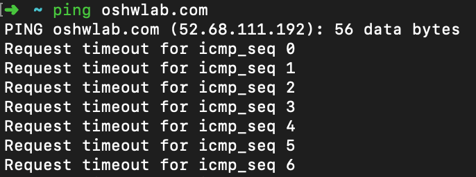
I’d like to have a look at the schematics. Unfortuately the one posted earlier linking to https://oshwlab.com gives a 504 Gateway Time-out. Can you provide an active link?
Hmmm OSHWLab seems to have tech difficulties altogether actually
Use this link instead: margarita prototype - EasyEDA
I’ll update the first post. EDIT: well, I can’t
Note that this schematic and pcb aren’t up-to-date but I’ll push the updates into public later today x
Sorry for the long gap between updates! I’ve been moving countries and had a ton of work in between (across different countries, too) which sort of slowed down this project a lot.
So, I’ve received a first batch and assembled one but ran into an issue, which I referred to here:
Basically, I’m thinking this is related to the VBus of the USB “switching”, because audio works but CV/knobs don’t get powered or CV/knobs work but audio doesn’t. I’ve been going over the circuit and schematic and I can’t see what the error could be. Confusing! Haha. I’m surely missing something.
But it looks like “CV” op-amps don’t receive 3.3V when Eurorack power is on and “audio” op-amps don’t receive VEE/VCC when USB is plugged (for uploading data).
 and so is the encoder… I think!