Questions about digital noise and grounding

I recently built a Terrarium, and I had been concerned that it might be noisy.

I’ve only run it from a 9v rechargeable power brick (except when flashing it from my Mac), and it sounds fine through a guitar amp. I’ve tried block sizes of 4 and 64, without noise related to block size. Of course, it’s a guitar amp/speaker, and my hearing isn’t all that great anymore…

When I first got a Pod a few years ago, I was bothered by the buzz at the frequency of the audio callback. I’ve now got several Daisy devices (patch.Init(), Bluemchen, DPT, Veno-Echo, Terrarium), and all are quiet in their intended setups. I’m inclined to think the Pod buzz was caused by powering it from my Mac USB, with audio going into the aux input on my AudioEngine speakers, which were also connected to the Mac USB.

Oh yeah, i have been through the same paces of trial and error.
I made some elaborate recordings of all Seed devices i could get, running them from wall warts, bench power supplies, internal and external USB and of course Eurorack and Buchla racks.
I have recorded a Field, a Patch, Petal, Pods on different power sources, the Aurora , the Nautilus (very sexy seeds btw) and finally our cardME and it took 0 PCBs to get it down to the level of the Aurora which is the quietest of them all.
I tried clever routings, dumb routings, 2 layer boards, 4 layer boards, balanced audio converters, transformers and what not.
And in the end, PETAL style power guts mixed with POD headphone hardware on a 4 layer board with 1mm (!) diagonal power lines and special grounding and shielding planes inbetween lead to a good result.
At one time i have a wire from the PCA LED driver running across the headphone amp section and I could head that LED in the mix.
Also powering the Seed with 5V is much quieter than higher voltages, so the onboard LDO is noisy too.
I have hope the new Seed V2 from the Aurora and other QBits units will be a bit nicer in terms of power-to-noise ratio.

Interesting, thank you for all the tips! I’m using the same PETAL style power guts so hopefully I’m on the right track with some of the changes I’m trying with my layout. My first suspect is that I have my GND from the 9v power jack and Isolated GND from the PDS1-S5-S5-M directly connected by a single ground plane that spans an entire layer of my PCB. Which from my new found understanding of how DC/DC Isolators work, kinda defeats the purpose. So, I’m hopeful that will help address the issue a bit.

I am powering the seed directly from the 9v power jack, so perhaps that’s causing some issues too, should be easy enough to test it with a 5v power supply instead.

Fortunately, it doesn’t seem that the LEDs or OLED screen are causing my issues. I’ve removed them both from the circuit and still have the issue.

The PDS1-S5-S5-M is connected to a big ground plane in my design as well.
But it has a dedicated 7805M to drive it and only powers the audio ICS, same as in the petal schematic.
But i routed the actual Seed power and ground in a separate trace 1mm each directly to my input power.
The additional analog hardware i use to tap into my 7 extra CV inputs also have their own star like routing to main power.
The big ground planes on both sides are more to isolate than to provide.
Also, make sure you do not do IC-hopping with your power.
Try hand routing a 0.6mm trace to each IC or at least each section so if one draws a lot of power for example when driven by an outside LFO in the 10V range the next IC can still run in peace if it has its own power.
Then, try to bundle up the audio part and avoid parallel audio and power traces…are are entering the realm of voodoo here, but after my LED-in-audio experience i try to follow all those old school routing guidelines…and yes…a 4 Layer board will help a lot as well…
If you are familiar with the late Mutable Instruments designs, they have moved all power routing to layer 2 and 3 and do the data routing on the outside only.
This is my power network on the inside layers…most of it is for the LED ring that i did not route manually :slight_smile:

1 Like

Thanks for the tips. I am working with a 4 layer board. Signals on the outer layers and GND on one inner layer and power on the other inner layer.

I tried another board with a few experiments. Routing the power and grounds (AGND and DGND) directly to the seed with their own traces didn’t seem to make any difference vs just using the big power and ground planes.

The other thing I tried, was completely isolating the GND for the analog parts of the circuit (basically the op amps and the surrounding circuits for the input and output buffers) to feed directly back into the 0V (isolated ground) on the PDS1. Basically I originally had the isolated 0V on the PDS1 connected directly back to the main GND plane (so that all grounds were shared on the board) like it shows in the Daisy Petal schematic:

Looking at the specs of the PDS1 it seems that typically those should not be connected and that the 0V should act as the isolated ground for any of the circuits using the Isolated 5V coming out of the PSD1. Like this:

I tried that in my updated schematic and that was a complete fail. It worked fine for the audio input circuit section, but for the audio output buffer from the SEED there was now a TON of noise. After some troubleshooting and discussion with Shensley, it sounds like the 0V coming off the PDS1 does indeed need to be connected to the shared ground because the seed analog circuits are coupled to that shared AGND which is also connected to DGND. So I guess it’s not possible to really fully isolate the input and output buffers from the rest of the circuit since somewhere those grounds will need to connect.

Anyways, I just wanted to share that tidbit, so no one else tries to use the PDS1 to fully isolate power and GND to their input and output buffer circuits. It won’t work. :slight_smile:

I came to this post looking for a solution to noise on a breadboard while learning Daisy.
The noise doesn’t occur with the Daisy powered by usb, but there was awful noise running from the power from the OMSynth.

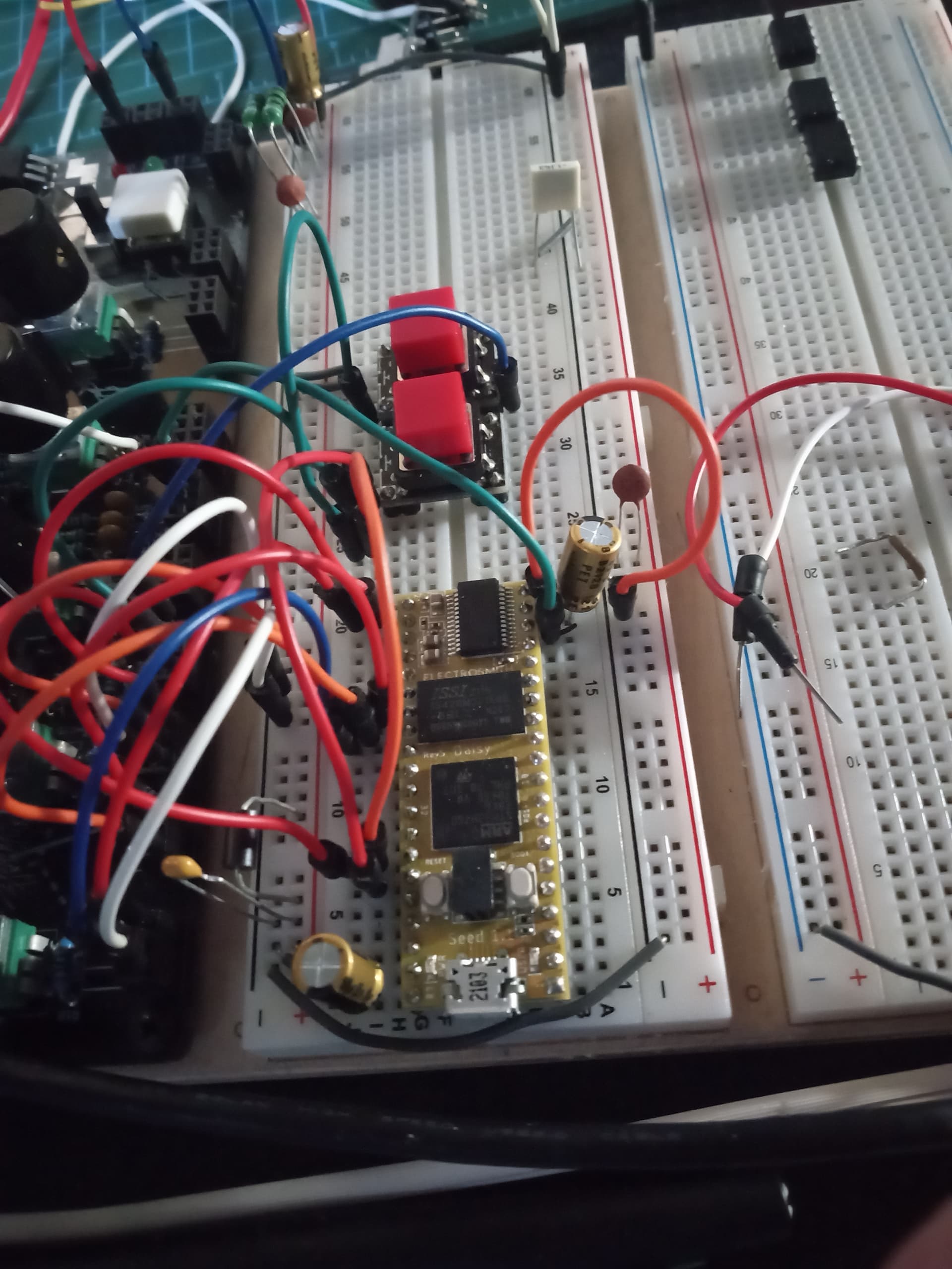
If you are like me, and just looking for a way to eliminate the noise while breaboarding and learning–a simple solution was found using 3 100uf electrolytic capacitors. (I used 100uf Nichicon PETs, not sure if these specifically helped or not)

Capacitor Negative Terminal Positive Terminal
Cap 1 Ground Rail Power Rail
Cap 2 DGND Vin
Cap 3 AGND AudioOUT2
(In the recently curated oscillator and drum examples, AudioOut2 is tied to ground.

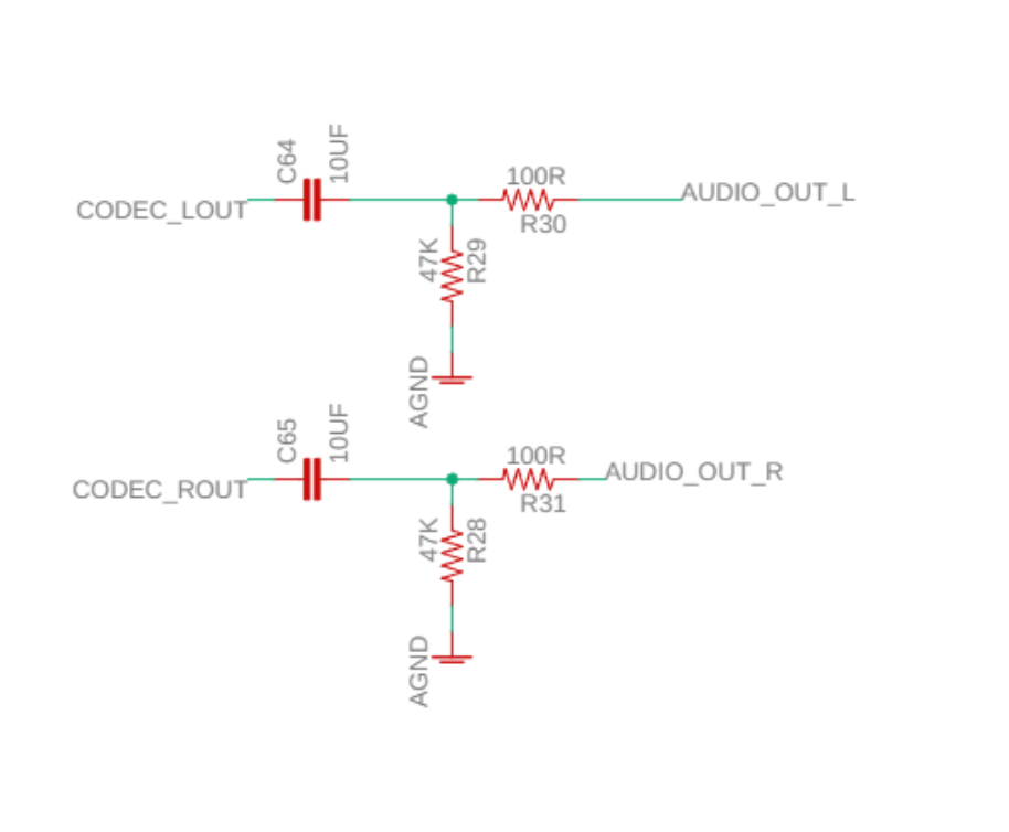
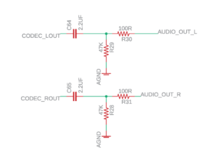
If you want to use both (AUDIo_Out 1 & 2), replace the 100uF electrolytic with a 100nF or such-like, preferably film…)

Connecting the capacitors:

Capacitor 1: Connect the negative terminal to the ground rail and the positive terminal to the power rail. This configuration helps stabilize the power supply and reduce noise by providing a low-impedance path for high-frequency noise to bypass the sensitive circuitry. The capacitor acts as a reservoir, smoothing out voltage fluctuations and reducing the impact of noise on the system.

Capacitor 2: Connect the negative terminal to DGND (Digital Ground) and the positive terminal to Vin (Voltage input). This configuration specifically targets noise in the digital circuitry. Digital components, such as microcontrollers or digital logic, can generate fast switching currents that introduce noise. By connecting a capacitor between the digital ground and the voltage input, high-frequency noise is filtered out, ensuring a clean power supply for the digital components.

Capacitor 3: Connect the negative terminal to AGND (Analog Ground) and the positive terminal to AudioOUT2. In some of the DaisyExamples, such as the new oscillator and drum demos, AudioOut2 is tied to ground. This configuration focuses on noise reduction in the analog audio output circuitry. By connecting a capacitor between the analog ground and the audio output, any noise present in the audio signal is attenuated, resulting in cleaner audio output.


I did this for just running a modified version of the oscillator example–so nothing super fancy–we’ll see if this is still effective with reverbs, delays, etc. However, there is no longer any blatant horrid audible noise at present, but still a slight hum, like a mosquito is in the room (we will squash this before the end)…

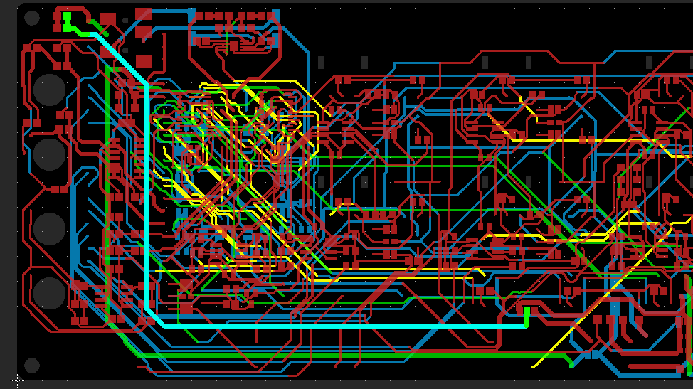
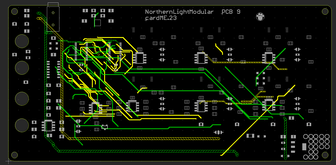
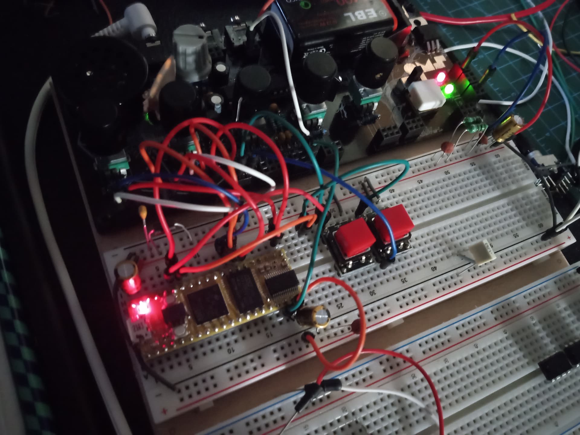
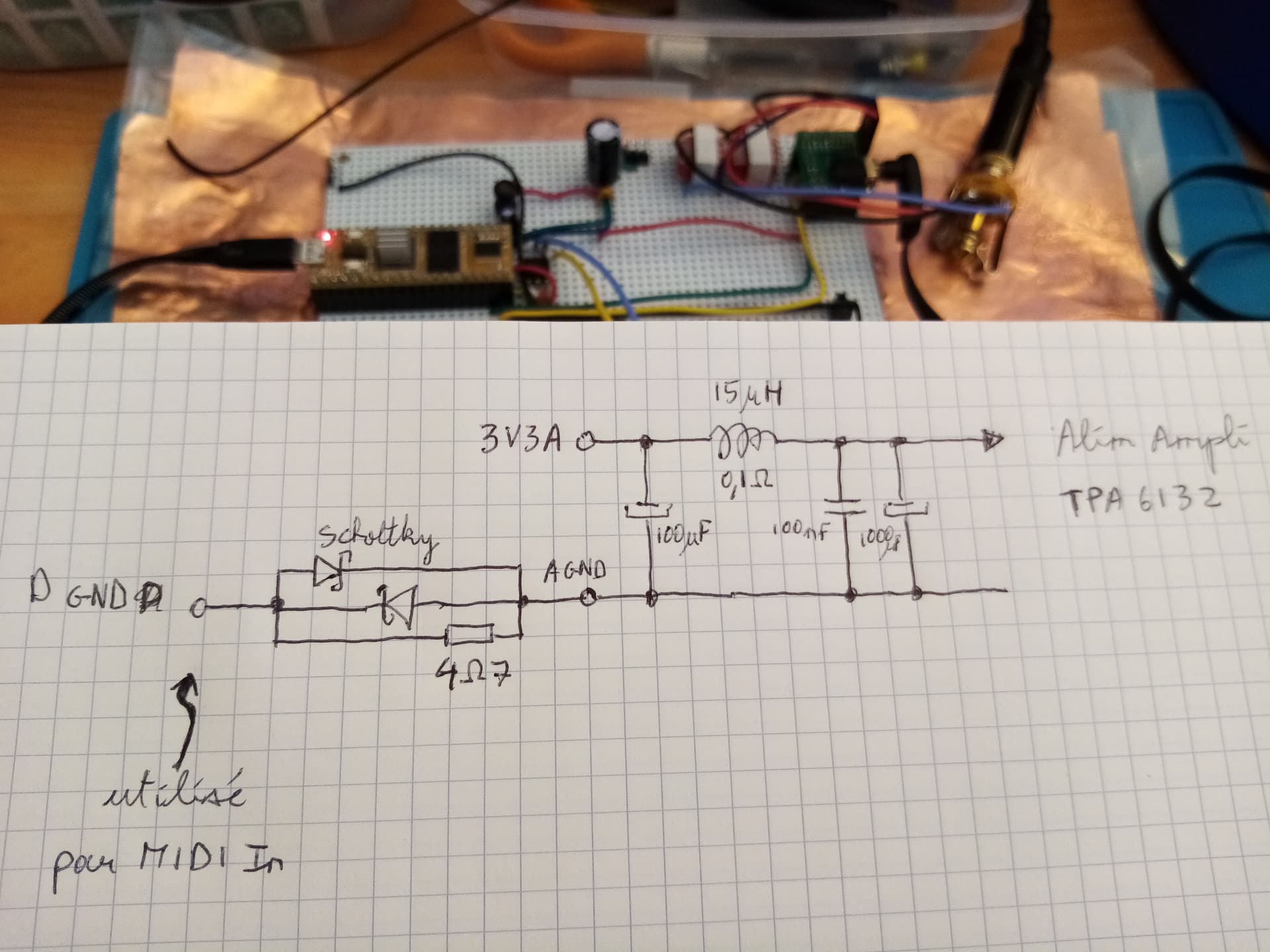
You may notice from the picture there are 100nf/0.1uf decoupling capacitors everywhere there is a spout from ground or power to the Daisy. There are also some near the power entry point (probably overkill, but this is a noise-elimination-extravaganza…) It also doesn’t hurt to add inductors/ferrite beads along the power rails (make sure the inductors/ferrites stay in their respective rail, or they’ll start to stink up your lab).

Decoupling capacitors:
Placing decoupling capacitors (100nf/0.1uf) at connections between ground or power and the Daisy board is a common technique to reduce noise. These capacitors act as local energy reservoirs, providing instantaneous energy to the circuit during sudden changes in current demand. They help stabilize the power supply by preventing voltage drops or spikes, which can introduce noise into the system. Decoupling capacitors also act as low-pass filters, attenuating high-frequency noise and ensuring a clean power supply for the circuit.

Inductors or ferrite beads:
Using inductors or ferrite beads along the power rails further enhances noise reduction. These components work as low-pass filters, impeding the flow of high-frequency noise while allowing the desired power supply to pass through. Inductors and ferrite beads have high impedance to high-frequency signals, effectively filtering out noise. Placing them correctly on their respective rails ensures they effectively filter noise without introducing interference.

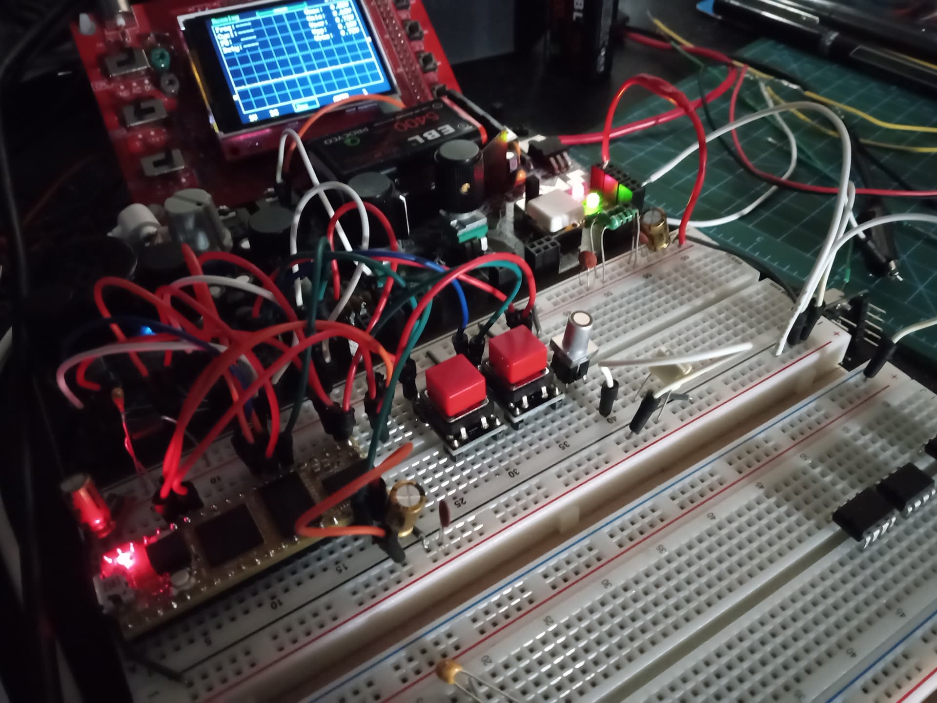
Finally, to remove that “mosquito-somewhere-in-the-room” noise–
–replaced the breadboard dunlop wires from the power supply to the breadboard with real wires with solder on each end:

Now, there seems to be no audible noise difference between everything off, and everything on, which is ideal!

Also, do not forget to disconnect breadboard power to Vin before connecting the USB for a new code upload!

I hope this helps anyone, especially those just breadboarding and learning–who may run into trouble with the :dotted_line_face: noise, and that they may not have to scour the net for many possible solutions for noise reduction while breadboarding.

Best

5 Likes

Thank you for documenting your noise elimination extravaganza and sharing an in-depth guide!! :slight_smile:

2 Likes

I figured out my noise issue! It was NOT related to the PCB or hardware design. It was because I was calling the Update() function on my LED from the main loop instead of in the AudioCallback function. I had been doing it this way because the simple LED examples for LibDaisy do it that way. However, none of them do any audio stuff, so they don’t have an audio callback. For whatever reason moving it to the audio callback gets rid of the noise!

Thank you for the update! I’m glad it wasn’t a hardware issue.

And that’s really interesting. My understanding was that it’s good to do most tasks in the main loop and spend as little time as possible in AudioCallback.

Yeah I was surprised, what tipped me off is that the LED code gets initialized with the sample rate. Every other libDaisy control that does too has and update or process function that gets called in the audio callback and it does work based on that same rate timing. I’m guessing calling in in the main function has the LED doing calculation with improper timing for the software pwm code as I was also pulsing the LED brightness. Not sure why that would cause noise though.

it seems to me that the capacitors C64 and C65 (audio output capacitors) are MLCCs .

Why MLCCs?

MLCCs are sensitive to almost everything!
(Even sounds and impacts).

Agnd and Dgnd were the ideal suspects, and i think we focused too much on them.

I think that the only serious solution to the infamous hiss issue is to use an external I2S audio Dac on SAI2 (which won’t use MLCCs on the audio path).

Class 1 non-ferrorelectric ( paraelectric) MLCC’s (C0G/NP0) are used for audio. They’re not microphonic like their ferroelectric “cousins” - the Class 2 MLCC’s (X5R,X7R etc.).

2 Likes

Thanks Jens Peter
So C64 and C65 are innocent.

I won’t try to short-circuit-them.

Probably, I haven’t checked the BOM - and there are different versions. Just wanted to comment that not all MLCC’s are “bad”.

1 Like

An update of the schematics i posted before.

noise level is quite low on one channel but can still be heared on the other.

Is there a way to check what kind of MLCC is actually installed on a board by a manufacturer/supplier/subcontractor ?

without hitting the board with various objects.

1 Like

I don’t think it’s possible to identify them.

But you could measure the electrical characteristics of the capacitor.
The various dielctric material react in characteristic ways to temperature, frequency etc.

Scroll down to " Electrical characteristics"

No comments on the TI article. Other than the author is a product manager for TI High Speed Amplifiers, he’s not claiming to be an expert on capacitors - does mention the C0G/NP0’s, but doesn’t seem to consider them as a replacement for the piezoelectric X7R… dunno, maybe they were not available when he wrote it.

Searched mouser for a 2.2uF C0G - only 1 (!) hit - datasheet from 2021

https://eu.mouser.com/datasheet/2/281/1/GRM155C70J225ME11_01A-1983655.pdf
(datasheet says X7S - dunno, I’m not an expert.)

1 Like

Yes there’s not much discussion about those.

By the end of part 2, he suggests to use C0G in parallel of other capacitors to compensate their higher ESR.

Thus i go back to tapping my daisy seed with my Bic pen. :blush:

I’m just guessing - perhaps the two caps on seed v4 (with AK4556) are X7R

and the two caps on seed v5 (with wm8731) could be C0G.

Maybe electrosmith will disclose the partnumbers used ?

1 Like

I think that’s consistent with the size of C0Gs vs X7R.