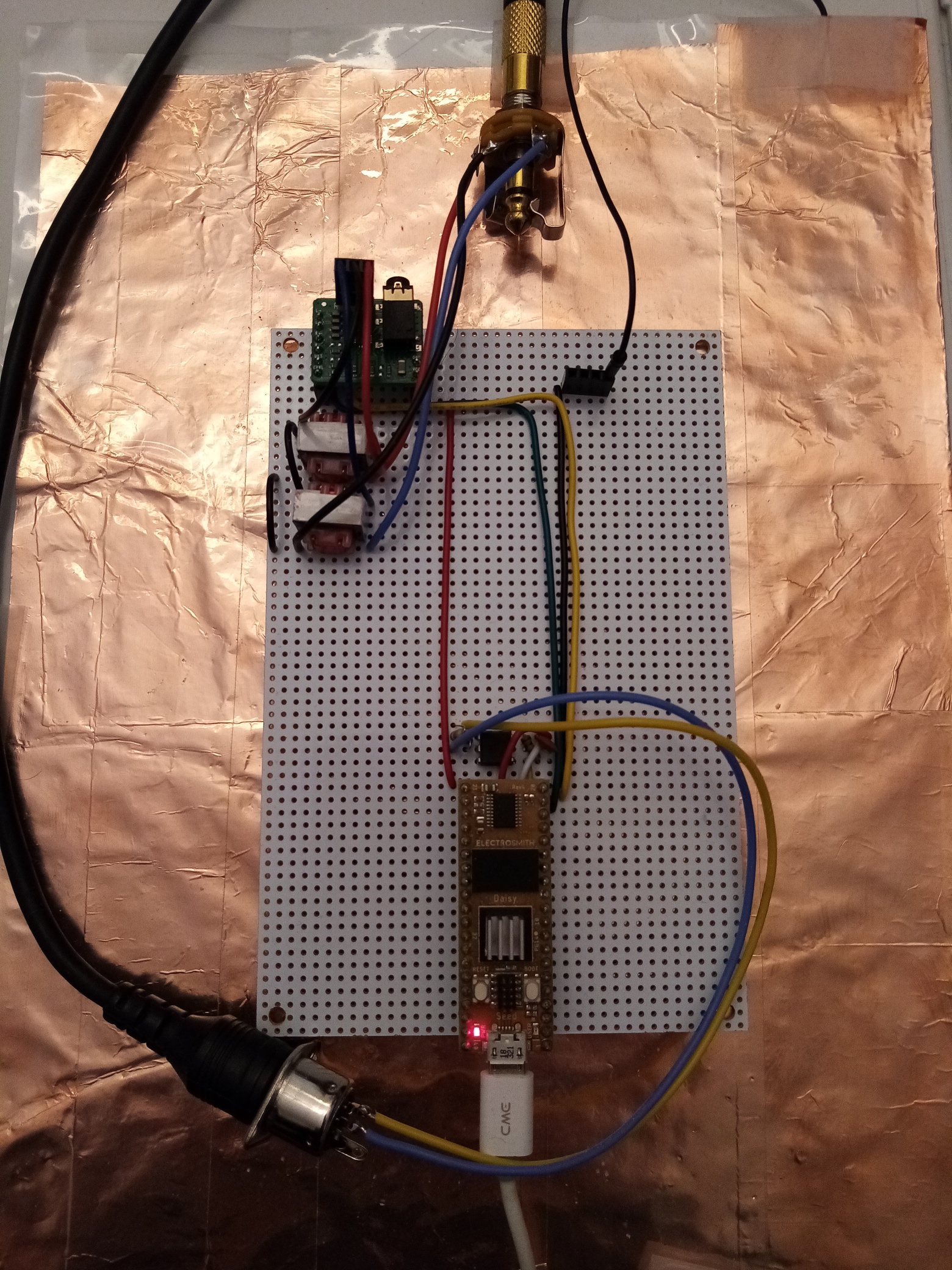
Here is my low cost solution and efficient to this ground loop issue :
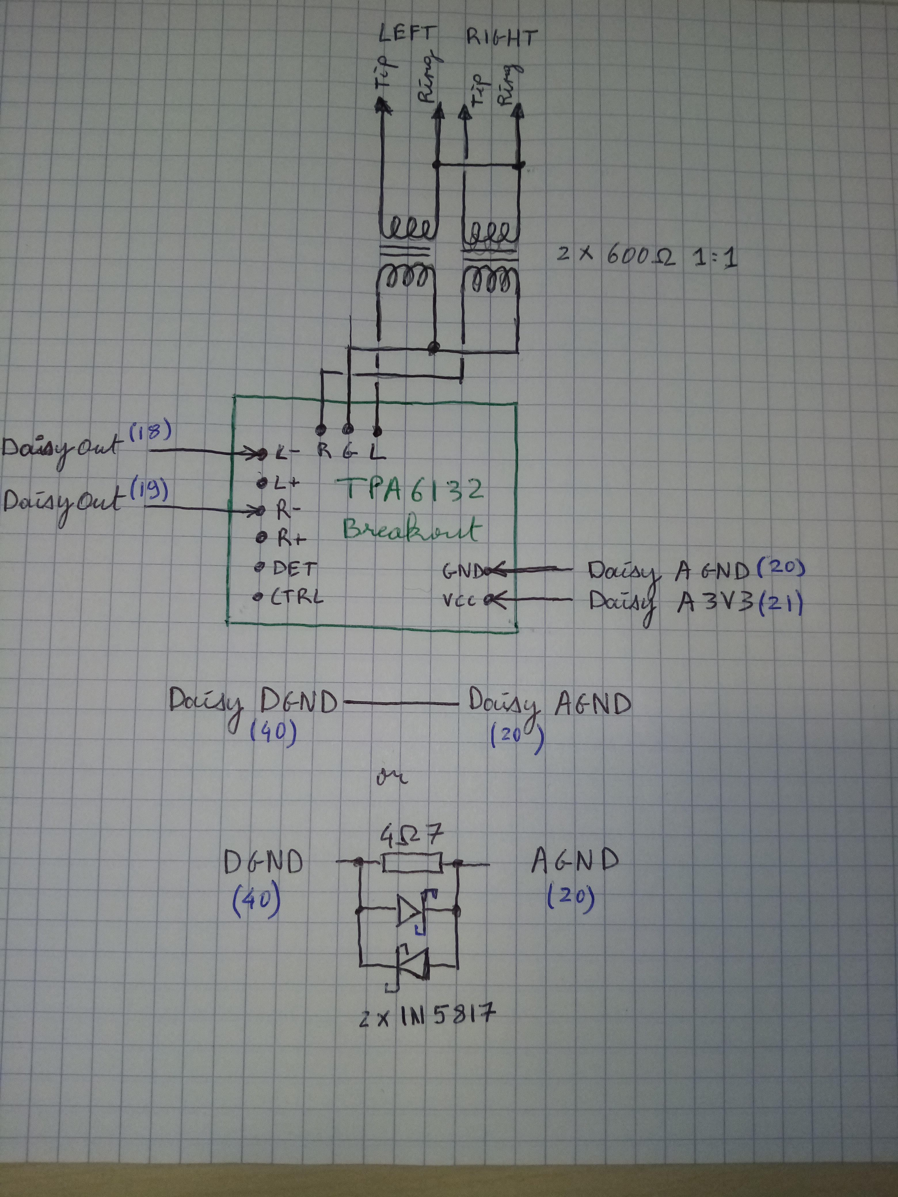
A TPA6132 (nice headphone amplifier from TI) breakout that drives a pair of 1:1 600ohm audio isolation transfomers (the same kind as in the HD400 and its clones).
What is everyone doing with AGND when designing PCBs for the Seed? Are you just connecting it directly to a DGND copper pour / plane? Or giving it a separate trace back to the power connector? I wonder how this would affect the noise?
Hey everyone,
I’m running into similar whistling noise issues with a Daisy Seed built into a guitar pedal format.
It’s definitely dependent on the sampling rate, can be shifted by reducing the block size but it’s still present (I’m usng a 78L05 to create a regulated 5V for my opamps but am not using a dc/dc isolator as is shown on the Petal schematic).
My issue is that the current draw affects the ground hence adding noise in the opamp buffers.
At the moment my DGND and AGND are connected.
I’ve been going through the comments and remarks here (in particular @SmashedTransistors ’ latest ones) and I’m wondering for a first test: if I place a 5R (or similar) resistor between the Daisy’s DGND and AGND, and share the AGND as common ground with the rest of my circuit (opamps etc), could this avoid a ground loop and alleviate the CPU whistle issue? A 15dB reduction would be nice, especially as I’m messing around with shimmer reverbs that tend to repeat, amplify and shift any input noise, making it rather noticable.
I don’t know if you saw the conversation between Mike and myself further up, but by spreading out the ADC calls in my code I was able to radically reduce the whistling.
In terms of hardware I do have the isolator however. I’d also be very interested to see what the affect of the 5R resistor between AGND and DGND would be. The only thing I have done so far is run the AGND back to the power connector (my design is a eurorack module) with a separate trace, and everything else is connected via a copper pour, including DGND. This does work well actually, but if there’s other improvement to be had I’d like to give them a go. I think I’m going to try a 4 layer PCB actually, with the 2 internal layers as ground planes.
Yes I saw the discussion above. I’m not too keen to follow that route because my Daisy codes are mostly generated using gen~/oopsy, so upscaling the sample rate and splitting code sections is a bit of a hassle (and I feel it’s a big effort for a workaround that should be able to be dealt with at least to some extent in the electronics rather than complexifying/tweaking code strucure).
I wanted to make sure I understood things right and that testing the 5R wouldn’t put the Daisy at risk, I’ve burnt one out before by being a bit too careless/hasty with hardware connections and I only have the one left at the moment, so I’m treading carefully…
As far as I experimented using the TPA6132 breakout and the isolation transformers is the only solution that solved the problem (as it actually breaks the ground loop, while a 5R resistor would attenuate the loop).
I think it is also the safest way to go as the daisy seed output is protected with the tpa breakout.
These breakouts and transformers are quite low cost and easy to find (i bought them from amazon).
[edit] if you go for separating AGnd and DGnd with a small resistor and worry about eventual damages caused by potential differences between them, you can add a pair of schottky diodes as described here. Their low threshold voltage will protect you from such hazards.
has anyone made progress on this issue? i’m amplifying the output from a Seed, but even with totally isolated power sources (one battery for the seed, one for a headphone amp) the callback noise persists. i’m working on some filtering now but it’s not going great. edit: making sure that potentiometer grounds take separate paths to ground from audio cleared that up! d’oh!
At last I reduced the audio blocksize to 3, so the callback frequency becomes 48kHz / 3 = 16kHz, basically inaudible. This worked fine for my application as a guiar pedal. Now I can put gain stage after Daisy and still get a clean output.
I think your code should be designed to do exactly what your design requires. If you have to modify your code to avoid hardware issues then the hardware needs to be improved.
i am fighting the same problems here and i am willing to go the extra mile using the TPA6132 straight up in my PCB.
Do you have a suggestion for a small 600:600 transformer to place behind ?
The ones used in the HD400 seems a bit big for what i had in mind.
I think I might be having some similar issues with the board I designed. I started experimenting with different sample block sizes and sample rates today. I noticed when changing from 48k → 96k sample rate it sounds like there is more background noise in the signal. It’s like the noise floor is louder than at 48k.
After reading this thread I have a couple of question about best practices:
Someone mentioned separately routing AGND directly back to the main power jack ground. Should things like pots that are using 3.3VA also have their ground connections routed separately from the regular ground plane?
I’m using the PDS1-S5-S5-M on my board to create the 5v isolated pwr for all the buffer circuits etc just like in the schematic for the Daisy Petal. All the buffer circuits etc are using that isolated power, however I’m just using the common GND plane for those circuits. Should all those circuits be using a separate ground that goes back to PIN 5 (+0v) on the PSD1-S5-S5-M instead? There is a note in the schematic that says “keep the 9v path clear, and direct to the seed. (lots of isolation, and ideally a separately routed GND)”. I have a clear 9v path directly to seed, but I’m just typing pin 5 into a big ground plane pour that is shared by everything, and I’m wondering if that’s an issue.
If you didn’t notice the noise before changing to 96kHz sample rate, then your circuit should be ok.
The noise that you’re hearing may be a result of the Daisy overworking.
Changing from 48kHz to 96kHz is going to pretty much double the amount of work the daisy is doing for any given program.
While this shouldn’t have much of an effect on the noise floor, a program that’s using more than 40-50% CPU at 48kHz could start to approach under-running issues in the audio callback when switched to 96kHz, especially with extremely low block sizes (2-24).
This would result in crackling or other noise-y artifacts.
I recommend increasing the block size (between 96-256) to see if it results in a positive change.
And profiling the CPU usage can be a good way of nailing down if the issue is in code or not. You can do so by calling .OnBlockStart() at the beginning and .OnBlockEnd() at the end of your audio callback. Then you can request the resulting load measurement and print it on a display or a serial connection. Please make sure to print from the main loop and not the audio callback itself.
Thanks for the response! I tried changing the block size to 96 and 256 and the same noise is still there. I really don’t think I’m approaching and sort of under-run situation either. Just to be sure, I changed my audio call back to simply pass through the dry signal as follows:
out[0][i] = in[0][i];
out[1][i] = in[1][i];
The noise is still present. I did also have some noise present prior to changing to 96k, it’ just less audible. I don’t think I can rule rule out the circuit quite yet. So far I’ve tried things like turning off all the LEDs on my board to no avail. So I’m wondering if my issue is indeed that I’m not using the DC/DC isolator properly because my grounds are connected instead of being isolated on the board for the different regions of the circuit.
If there’s still noise even with a bypass code like that, then it could be the circuit.
I suggest trial-and-error-ing different ways that you can ground which you listed earlier.
Also, is this for the pedal with the OLED? There were several discussions about noise caused by that on the forum, which could be worth looking into.
If there are other possible causes of the noise, please feel free to share.
This happens to both my oled pedal and the one without. I’ve got a board on order with a different ground strategy. Going to see if that makes a difference. Also changed a few things like routing AGND directly back to the power jack ground as someone recommended in this thread as well. Fingers crossed
I may be chasing a ghost. The Terrarium hardware does the same thing for me too (not that it has the best grounding strategy itself). I ruled out my power source too. Happens when powering with even just a 9v battery.