Questions about digital noise and grounding

Hi there,
I’m working on a project with guitar pedals, and the daisy seed will be used with pedals that have a lot of gain like an overdrive. Now my problem is that, there is an annoying high-pitched noise coming out of the audio output, and the noise occurs around 5~6 times a second. Which is exactly the refresh rate of the LCD display I hooked up to daisy seed. (It’s kinda cool to “hear” the fps :joy:) The noise becomes unbearable when a lot of gain is applied.

However, when I disconnected AGND and DGND, the noise disappears, and everything seems to be working fine. But everything I’ve read so far suggests that AGND and DGND on the seed should connected together. Should I just keep them disconnected, or there are other ways to reduce digital noise?

2 Likes

They should be a connection at some point. Generally a significant voltage difference between AGND and DGND should be avoided, this could damage some circuit.

Anyway I have the same issue here. The processing callback produces a high pitch tone, and switching a low-power LED emits a distinct pop. I would be interested by any kind of solution to improve this, too.

In the meantime, I’m using a software multi-band noise gate to filter the signal at the input. It works great, I’ll clean up the source code to remove external dependencies in the next days and will share it.

2 Likes

Well, I connected a 1000uF capacitor to VIN and ground, and the noise reduced by about 50%. Still quite noisy for my use case though. Maybe there is a way to separate the power supply of the ADC/DAC and the rest of the components?

@Firesledge Looking forward to it! Thanks for sharing.

1 Like

Well, I connected a 1000uF capacitor to VIN and ground, and the noise reduced by about 50%. Still quite noisy for my use case though. Maybe there is a way to separate the power supply of the ADC/DAC and the rest of the components

I am just finishing up a guitar amplifier and ran into the same problem. Just like you, I installed a 1000uf capacitor at Vin. I ended up putting in 2 additional capacitors. A 0.1uf also at Vin and a 220uf at 3.3v. Be super careful about grounding. Even though AGND and DGND are tied together, don’t allow any return current from your digital devices to flow through any part of your analog return paths (the audio and any potentiometers you may be using). Good luck. I hope you get it working satisfactorily.

2 Likes

Yes, these are good advices. My capacitors were 100 µF, but I’ll try with larger capacitors too.

Anyway here is my noise gate code. All the instructions are in comment in the main.cpp file, but I’ll reproduce them below too:


Noise gate example and calibration application for the Electro-Smith Daisy

NoiseBleach is an 8-band noise gate. It is some kind of intermediate solution between a standard noise gate and an FFT-based noise removal. It has more or less the best of both worlds.

Each frequency band has its own threshold and gate time. The former can be configured at any time, and the latter is automatic.

Even if the default configuration works, you should take the time to calibrate the gate and find the optimal values for your hardware settings.

Compile with:

C_INCLUDES ?= -I.
C_DEFS ?= -DNDEBUG
OPT ?= -O3

You may have to add CPPFLAGS += --std=c++14 too, but this should work without it on any recent compiler.

The code makes intensive use of debugging assert(), so remove them with -DNDEBUG in production. A single channel uses about 14% of the CPU with a block length of 48 samples. You can reduce the number of bands to save CPU, but this will lower the noise efficiency.

This class was initially part of a larger code base, hence the weird dependencies I tried to group and minimize. It’s not made for Daisy but the portable parts including the DSP bits work fine, or require minute adjustment.

Calibration procedure

You’ll need:

  • The regular audio source for your setup (a guitar, a console output, whatever). Of course you can do it without, it’s just that it won’t take the source noise into account, only the Daisy environment.

  • Something to record the output of the Daisy. No super spec is required, just the bare minimum.

  • An audio file editor to check the recording, preferably with a spectral display (it’s easier but not mandatory at all)

  • And of course your Daisy hardware.

First, set the #define CALIBRATE_NOISE_BLEACH after the #include list in main.cpp. Compile and upload the program to your Daisy.

Run the test with an instrument plugged to the Daisy Seed left input. It should remain as silent as possible (put a sock between the strings of your guitar) but not muted at the volume pot.

Record the output and press the Reset button to start the run. Wait for 4 minutes and stop the recording.

Open the file in your audio editor. For simplicity, trim the file at the reset “plop”. This will be easier to measure the time offsets.

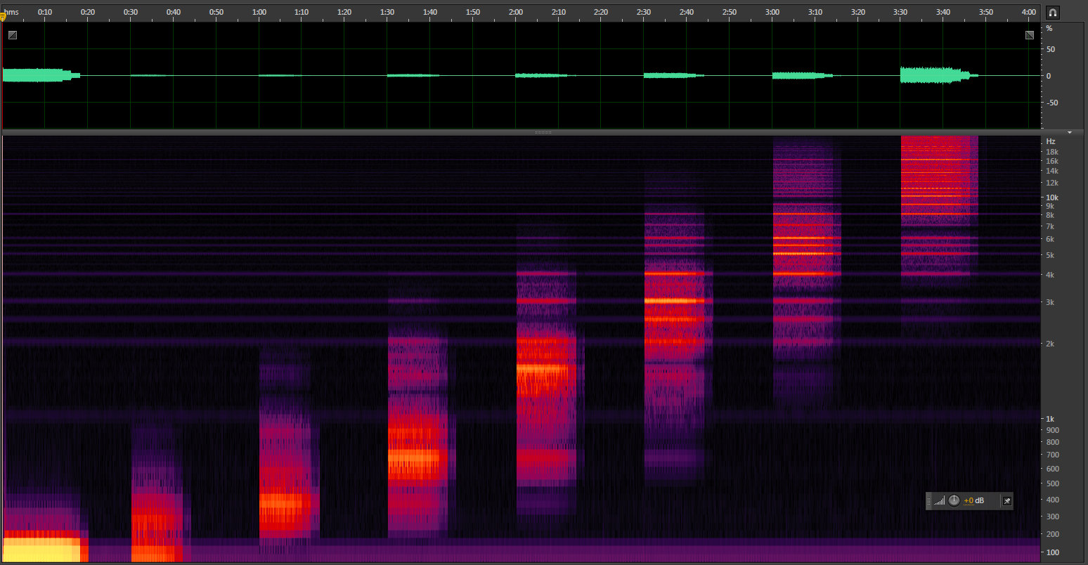
The 8 frequency bands are swept in ascending order, one after each other. They starts from -144 dB and the threshold is increased by 6 dB every 2 seconds. There are 15 steps, so this is 30 s per band. Normally, each band should start at full volume. At a given time, it starts to fade out step by steps, then finally becomes silent.

For each band, find the moment where it becomes silent. It’s easier to check with a spectral display rather than a waveform. Subtract this moment from the band time offset. Divide by 2 this duration in seconds to get a step index, multiply by 6 to get a dB value, then subtract 144. This is your threshold level in dB. Then convert it to a linear scale.

step      = (time_silence - time_band_beg) / 2
level_dB  = 6 * step - 144
level_lin = pow (10, level_db / 20)

Once you’ve done this for the 8 bands, report the value in the nzbl_thr_arr array which is used to initialize the NoiseBleach objects. You can tweak the value at your taste to let pass a bit of noise and increase slightly the sustain.


I also have a class called NoiseChlorine, working the same way but with weaker filters, and lower on CPU load. If anyone is interested, I can share it too.

1 Like

Maybe you should add a line filter/blocking/choke inductor in series of the + powering the display.

With the capacitors and inductor you get a second order low pass filter (not a bandpass filter! the capacitor and the inductor should never be put in parallel). Maybe add a resistor to avoid overshoot/resonance depending on the sqrt(L/C)

Note that big capacitors have internal resistance that limit their HF efficiency.

I did some more tests. Indeed, a large (1000 µF) cap on VIN helps a lot, but we’re still far from the goal. Adding a 100 nF ceramic cap as close as possible to the Daisy pins improves the noise performance from a tiny bit in the high part of the spectrum. There is no effect with a cap on +3V3_A, and for some reason things get worse with a cap on +3V3_D. Also, I’m still on a breadboard, so these results may become different on a PCB with real ground planes.

2 Likes

I’ve used a separate power supply for external devices, so now the Daisy Seed gets a dedicated power source. The noise improved quite a bit, but there are still high-pitched noise when drawing frames for the LCD. And it gets worse when I run Reverbsc with the display. Maybe the processr itself emits noise when it’s busy running particular tasks. :thinking:

About beads/inductors.

Re. some of the highpitched digital noise. The STM32 chip is actually a little too good at regulating its own power consumption. So there is a transient in current draw when the doing periodic things (like processing audio in the callback). This causes a slight lift in the GND signal that can create this digital noise (most audible at the callback frequency).

A bandaid that works when doing fairly trivial DSP is to increase the callback frequency to something outside of, or at the upper limits of human hearing. Obviously this is not always possible.

What we did on the Petal, and Field hardware (similar to on the Patch, etc.) is to use a DC-DC Isolator to create an isolated 5V supply that powers the Audio parts of the circuit (Buffers in this case). The daisy is then powered from 9V directly, keeping any noise on the 9V power brick instead of the audio path. (On the Daisy Patch we did the opposite – powering the Daisy Seed from an isolated supply, while the rest of the circuit and eurorack power stays clean).

The PDS1-S5-S5-M has worked well for this (5V-5V isolator), as has the PDS1-S24-S5-M (24V-5V isolator – used on the Daisy Patch)

The circuits for both the Patch and Petal are up on the Hardware Github Repo

10 Likes

“A bandaid that works when doing fairly trivial DSP is to increase the callback frequency to something outside of, or at the upper limits of human hearing. Obviously this is not always possible.”

Actually this is what I always do on other processors - I calculate the latest DAC samples at 96kHz and have a counter that increments by one to choose what else to do during the sample. Divide by 8 and a Case statement usually works fine.

And I was wondering for a second why this code looks so familiar…
It’s surreal bumping into you here. I’m still using your FFT anytime I need one, it’s the most usable implementation out there.
Looking forward to trying your noise gate.

2 Likes

To try and move the 1kHz noise (from 48kHz sampling and blocksize = 48) above audible frequencies it is pretty easy to lower the blocksize. Is anything bad going to happen or degrade if I make the blocksize 1 of 2 or something super low? Maybe processing will just go up? How was 48 chosen to be a good blocksize to start with?

The 48 blocksize was chosen as a way to have an easily understood callback rate (48000Hz / 48 = 1000Hz – or 1ms), that can still benefit from block processing while maintaining minimal latency.

Any effects from reducing blocksize would largely depend on how busy your process loop is, as well as how much stuff you need to do outside of the callback. Whatever is happening in other interrupts, or in the main infinite loop will be getting interrupted more frequently. This most likely would have a negative effect on stuff like USB or SD Cards more than anything else.

But if all you’re doing is generating audio then there may not be any issue.

3 Likes

I’m having some trouble with the noise issue as well. I’ve designed a eurorack module around the Seed, and have incorporated the isolator and caps in almost exactly the same configuration as the Patch. I was also able to reduce the block size down to 10 in my code without problems, but that still puts the whistling noise at 4.8kHz. Both of these things helped a lot, but I still find that I need to apply a 10dB cut with a Q of 18 in Ableton to make the noise inaudible.
Does the problem stem from the fact that the audio codec uses the same VCC and ground pins as the MCU? I wonder if using an external codec with better supply trace routing might solve the issue?

That’s one solution. Other is to try to get the block size down to 1 by dividing your code up into segments that are spread over 8 or 16 callbacks.

1 Like

oh that’s interesting, I didn’t think of that. My code has a combination of delay lines (reading from the SDRAM), filters, cross fades, ADC reads, digital outputs etc, so if I spread those around a number of callbacks the processor might be able to keep up? Presumably I would need to read the audio input on the first callback, and then end up writing the output on the last?

Yes it’s almost the same amount of code, you just add a counter from 0 to 7 or 15, increment it each callback and then test it and run that portion of the code. Just divide it up into 8 or 16 functions. If you can keep each function of similar time - the better you do this the quieter it will be.

You still read the audio in and write the audio out every callback. You get rid of the buffer (set it to 1)

I’m not quite sure how that would work - if I read and write the audio every callback it won’t have calculated all the data for the output? I mean it’s ok for dry signal, but for the wet signal (my code is a delay effect) won’t it run in to problems?