Is there a resource for how to use JSON pin names when using PD2dsy?

Apologies if this is in the incorrect place. I’m just starting out with getting pure data patches onto my Daisy Seed and I’m a bit stuck when it comes to the IO naming and JSON.

I understand setting up the custom JSON in order to use different IO on the Daisy Seed but I’m not sure how to format it, what pin names to use and then how to call these in Pure Data itself. Is there any reference anywhere for use with different types of input and output?

Hey mrlargefoot!

You came to the correct place! I wrote a quick tutorial over on our discord server, so I’ll migrate it over here for you. We’re planning on making a video about in the near future (I actually have the script done), but this guide should get you started.

Here, we have a [receive] object that has “knob” as an argument. The idea is that we want that object to output 0.0 to 1.0 when we twist a potentiometer that’s connected to the Daisy in the physical world.

knob_pd2dsy

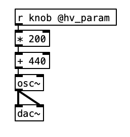
But, flashing this patch without any custom JSON won’t do anything. So, let’s have a custom JSON that will get this working!

Here’s customseed.json


{
    "name": "customseed",
    "som": "seed",
    "components": {
        "knob": {
            "component": "AnalogControl",
            "pin": 15
        }
    }
}

You can copy and paste this into a .txt file (plain text and not rich text) using TextEdit for example. And you can simply change the extension from .txt to .json.

You may have noticed that there’s “knob” in this JSON file. As you guessed it, that corresponds to "knob" in the [receive] object!

But how does it know which pin the potentiometer’s analog out is connected to? That’s where that "pin": 15 comes in.

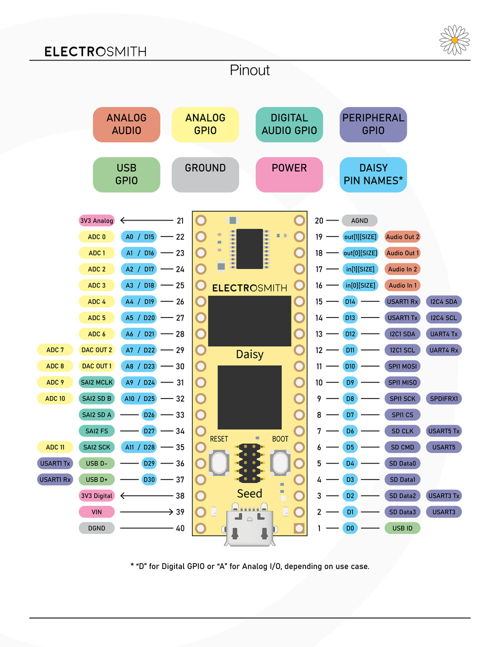
pin 15 corresponds to ADC 0 on the Daisy (please see the attach diagram. A0 = D15). I’m assuming you have a bit of Arduino experience (if not, no worries! I’m going over the electronics basics in the video), so that’s where the potentiometer’s analog out pin should be connected to.

So! After connecting the potentiometer to ADC 0, 3.3 volt, and ground (also don’t forget to bridge the DGND and AGND together for the analog value to be read effectively) and getting the .pd and .json selected in pd2dsyGUI (or plugdata), you can simply flash to the Daisy. I’m just gonna assume that you have the audio jack connected to the Daisy (I show this towards the end of the recent pd2dsy setup video, but I’ll go over this in more detail in the analog IO video).

After the program is flashed, you can twist the knob and the pitch of the oscillator should change!

What about adding more sensors?
Here’s an example of what that would look like!

{
    "name": "customseed",
    "som": "seed",
    "components": {
        "knob": {
            "component": "AnalogControl",
            "pin": 15
        },
        "ribbon1": {
            "component": "AnalogControl",
            "pin": 16
        },
        "ribbon2": {
            "component": "AnalogControl",
            "pin": 17
        },
        "fsr1": {
            "component": "AnalogControl",
            "pin": 18
        },
        "fsr2": {
            "component": "AnalogControl",
            "pin": 19
        }
    }
}

Let me know if you have any questions!

I can also talk about digital ins (like buttons) and DAC (CV outs) if you want.

Thansk Takumi, that’s super helpful.

I think I understand the syntax and naming, particularly the naming of the “knob” component and how that relates to the PD patch, as well as the pin itself.

I’m still a bit unclear as to what other types of IO there are and what naming to use for them. For example, where you have “AnalogControl” in the JSON, are there similar strings to use for analog out (CV) as well as digital IO like buttons, switches and LEDs?

Thanks again, this is a really exciting project. I wish this was available back when I was in University!

This page includes a list: Pd2dsy JSON · electro-smith/DaisyWiki Wiki · GitHub

It’s also good to reference the json file of Patch, Pod, and etc: json2daisy/src/json2daisy/resources at main · electro-smith/json2daisy · GitHub
I often do this.

Let me know if you have any questions!

I wish the same thing too!! So it’s always awesome to see current college students using the Daisy for their school projects :slight_smile:

Hi Takumi,

would be great to have more info (tutorial maybe?) about digital IO and all other pins like peripheral GPIO to understand the full potential of the Daisy.

Here are some of my noob questions for example:

  1. In the Component reference is stated that CVOuts are usually converted to 0-5V. Why is there a word usually? :slight_smile:

  2. Switches are digital? I managed to make a button work with analog pin 20.

  3. There are altogether 12 IOs for potentiometers, buttons, leds, gates and cvs. Is it possible to get more analog/digital IO with some breakout boards?

  4. Is it possible to get more CV outs than existing two?

Thank you

Hi mirko!

Yes, we’re preparing for bunch of video tutorials! But in the meantime, let me know if you have any questions.

  1. The Daisy Seed outputs 0.0V-3.3V out of its DAC outputs. And on boards like the Daisy Patch, that signal is amplified to 0.0V-5.0V.

  2. The Daisy (unlike Arduino) has GPIO pins. So pin D20 can be analog input or even digital output. Also worth noting that, even if you decided to use pin D20 as analog A5, it doesn’t care if you’re using an analog component like potentiometer or digital component like a switch as long as the voltage coming in is 0.0V to 3.3V range.

  3. Cd4051 Multiplexer Tutorial Is Here!

  4. If you’re using DaisyDuino or .cpp, it’ll be easy: Let's Add 4+ More DACs/CVs with Quad DAC! (Also, I2C tips!)
    For pd2dsy and Oopsy, I haven’t looked too deep into it.
    In general, a component like the MCP4922 is recommend for adding more DACs.

1 Like