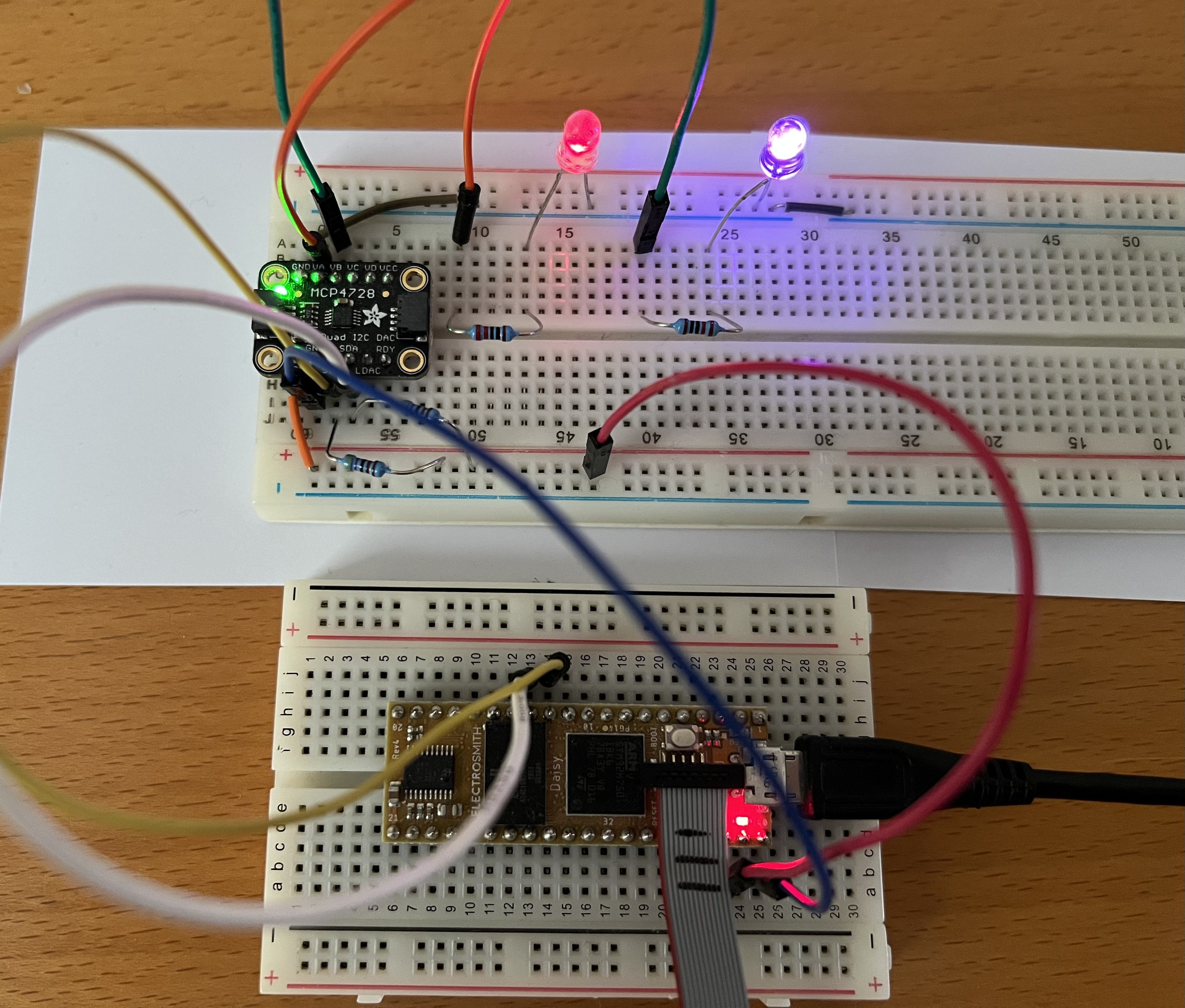
With Adafruit’s MCP4728 Quad DAC, we can add 4 more DACs to Daisy Seed with relative ease!!

2 of the DACs in action
You can see this I2C breakout board being used to send CVs to modular synths in this video.
It’ll be perfect for sensor-based Daisy instruments!
Let’s learn how to use it!!
What Do We Need?
-Daisy Seed
-Breadboard
-Soldering tools
-Two 4.7k ohm resistors
-Adafruit MCP4728 Quad DAC
-Jumper wires
-LEDs and 220 ohm resistors (for testing)
-Multimeter (for testing)
To get started, solder header pins to the Quad DAC (honestly the hardest step of all of this!).
We’ll be programming in Arduino IDE since there’s an external library that’ll make our job easy.
Let’s Connect!
It’s pretty straightforward to connect the Quad DAC to Daisy! Follow this diagram.
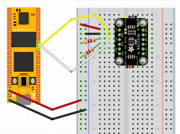
One important detail to remember is that Daisy does not have a pull-up resistor so whenever we use an I2C component like the Quad DAC, we need to use 4.7k ohm resistors like shown in the diagram. And make sure to use the I2C1 pins.
That’s about it! Let’s test this thing.
Let’s Output Voltage!
Let’s first light up some LEDs and then measure the voltage with a multi-meter. Once we are 100% sure that it’s working as expected, then we can connect to our (expensive) modular rig.
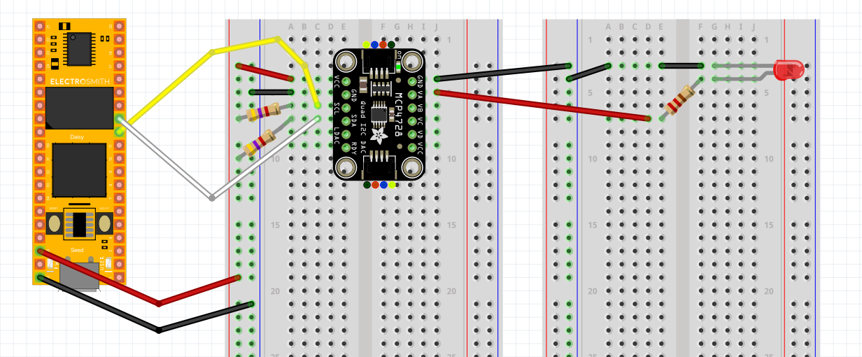
Connect an LED like this. Let’s just start with 1 or 2 for now. I’m using 220 ohm resistors here.
Let’s open up the Arduino IDE next.
First, install the MCP4728 library. Sketch → Include Library → Manage Libraries → Search “MCP4728” and install “Adafruit MCP4728”
Copy this into the IDE.
// Basic demo for configuring the MCP4728 4-Channel 12-bit I2C DAC
#include <Adafruit_MCP4728.h>
#include <Wire.h>

Adafruit_MCP4728 mcp;

void setup(void) {
  Serial.begin(115200);

  while (!Serial)
    delay(10); // will pause Zero, Leonardo, etc until serial console opens

  Serial.println("Adafruit MCP4728 test!");

  // Try to initialize!
  if (!mcp.begin()) {
    Serial.println("Failed to find MCP4728 chip");
    while (1) {
      delay(10);
    }
  }

}

void loop() {
    mcp.setChannelValue(MCP4728_CHANNEL_A, 4095);
    mcp.setChannelValue(MCP4728_CHANNEL_B, 0);
    mcp.setChannelValue(MCP4728_CHANNEL_C, 4095);
    mcp.setChannelValue(MCP4728_CHANNEL_D, 2000);
}
We can change the DAC voltage with mcp.setChannelValue() in the void loop().
For example, having the value “4095” in mcp.setChannelValue(MCP4728_CHANNEL_A, 4095); will change the 1st DAC’s output (Channel A AKA “VA”) to 5 volts.
Your LEDs may light up as soon as you wire everything up. If so, change the voltage value to 0 for testing purpose.
Hit upload to flash this program into Daisy. Once it’s done, open up the Serial Monitor. You should see the brightness of LEDs change.
If you see the message “Failed to find MCP4728 chip”, your components may not be wired correctly.
In order to see the effect without having to open up Serial Monitor every time, just comment out or delete these two lines.
  while (!Serial)
    delay(10); // will pause Zero, Leonardo, etc until serial console opens
Next, let’s use a for-loop to create a more animated effect!
// Basic demo for configuring the MCP4728 4-Channel 12-bit I2C DAC
#include <Adafruit_MCP4728.h>
#include <Wire.h>

Adafruit_MCP4728 mcp;

void setup(void) {
  Serial.begin(115200);
  /*
  while (!Serial)
    delay(10); // will pause Zero, Leonardo, etc until serial console opens
  */
  Serial.println("Adafruit MCP4728 test!");

  // Try to initialize!
  if (!mcp.begin()) {
    Serial.println("Failed to find MCP4728 chip");
    while (1) {
      delay(10);
    }
  }

}

void loop() {
  for (int i = 0; i <= 4095; i+=2){
    mcp.setChannelValue(MCP4728_CHANNEL_A, i);
    mcp.setChannelValue(MCP4728_CHANNEL_B, i);
    mcp.setChannelValue(MCP4728_CHANNEL_C, i);
    mcp.setChannelValue(MCP4728_CHANNEL_D, i);
    delay(1);
  }

}
(Nice!! But purple LED may have a different resistance? idk. But you get the point!)
MORE POWER!!!
I thought I was done at this point, but then I realized, “Wait, I’m using a 3.3 volt power so…”. After I checked with my multi-meter, the Quad DAC was outputting with the maximum voltage of 3.3 volt as I suspected (even though the value is set to 4095).
No need to panic! We can just power Daisy externally ![]()
I simply took out an Arduino Uno and connected its 5V pin to Daisy’s Pin 39 (VIN). And I also connected Arduino’s ground to Daisy’s ground. See this diagram for reference.

Good enough for testing! Ideally, do this with an external battery.
By the way, it should still be safe to connect Daisy Seed to your computer via USB even while it’s powered externally. I did double check this!!
Now it’s outputting more than 3.3 volt!! ![]()
What’s Next?
Once you’re certain that everything is working as expected, you can grab a 3.5 mm jack and start controlling your modular synths with Daisy!!
Because it’s I2C, we could add even more DACs by connecting another Quad DAC and changing its address.
Please let us know if you end up using this in your project!!