Cd4051 Multiplexer Tutorial Is Here!

Daisy Seed comes with 12 ADC pins.
But what if you need more??

Introducing cd4051 multiplexer!

Multiplexer_4051

In short, this multiplexer will allow us to turn 1 ADC into 8 ADCs. Let’s learn how to use it!!

How Does It Work? :thinking:
Ok, this thing looks…a bit intimidating. There are lot of pins and they’re not labeled like in a typical breakout board.

So, let’s have a look at a diagram like this.

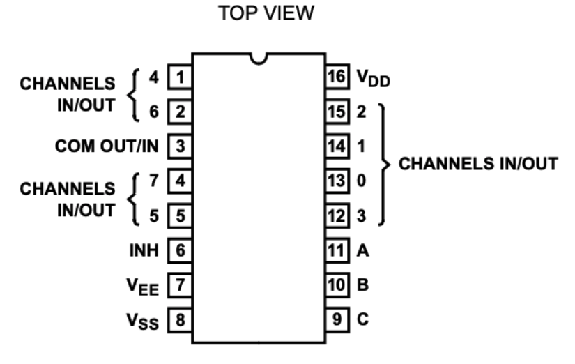
Still a bit daunting, but we are getting closer to understanding how it works!

Let’s have a look at pin 3, which is labeled “COM OUT/IN”. For our purpose of expanding the ADC, that’s the pin where we connect Daisy’s ADC.
So, let’s connect to ADC 0!


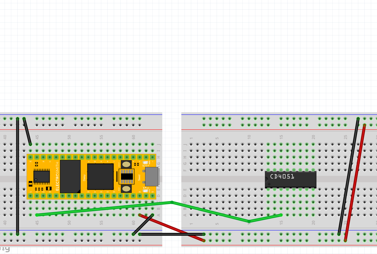
Green wire is Daisy’s ADC 0 pin

Next, we see those “Channels I/O” pins with a number next to each. For our purpose of expanding the ADC, think of these as the expanded ADC.

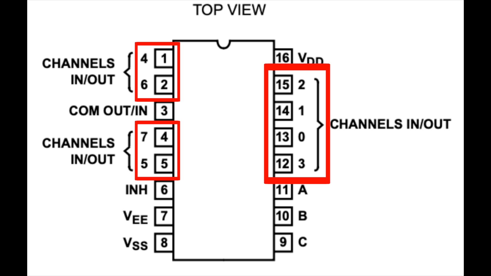
For example, we can connect a potentiometer’s analog out to pin 13, which we can think of as input 0. Then, we can connect a 2nd potentiometer to pin 14, which we can think of as input 1. And so on up to 8 total inputs!
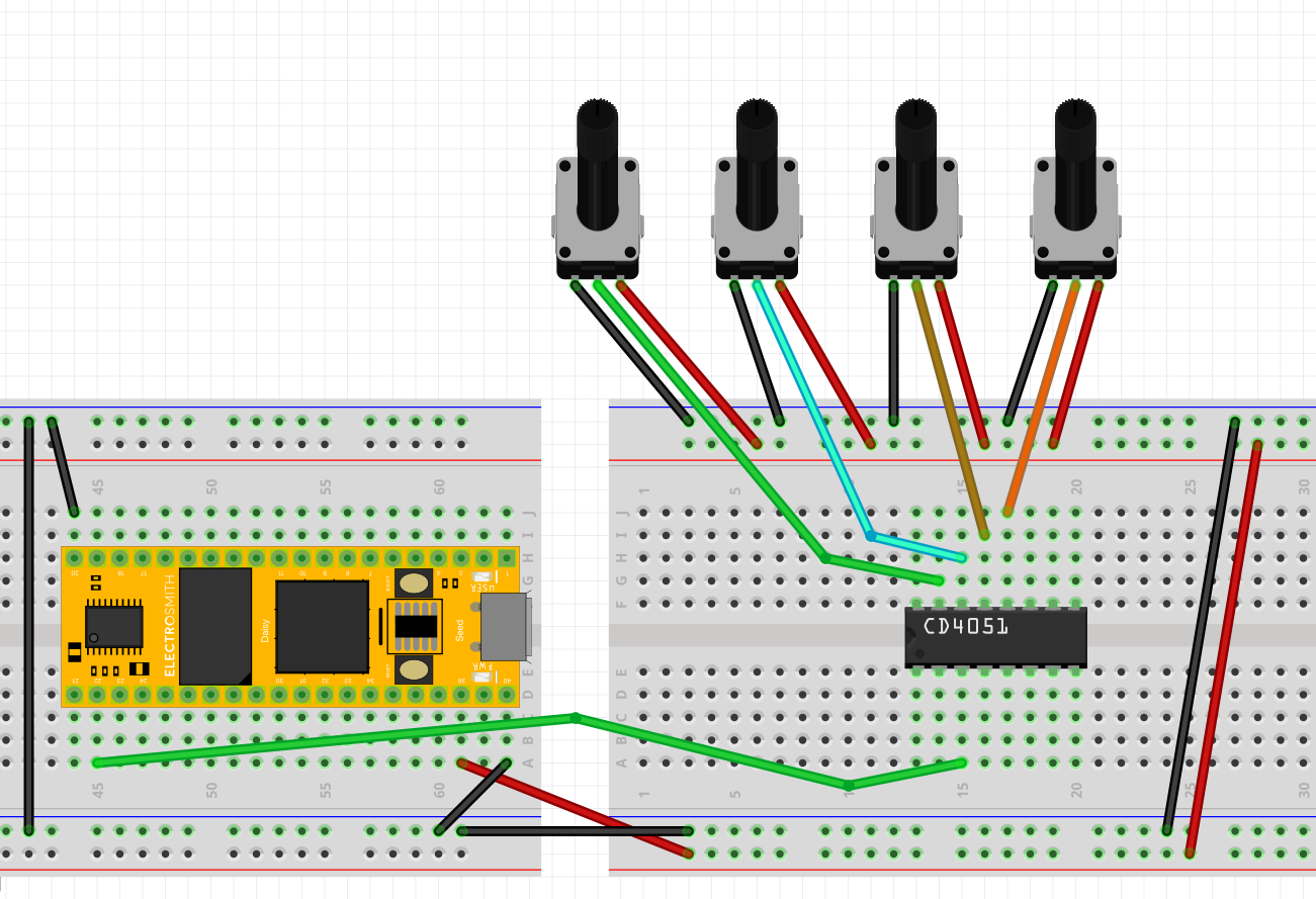
Let’s start with 4 potentiometers for now. Edit: I should’ve used 3V3 Analog for the potentiometers instead of using 3V3 Digital for both CD4051 and the potentiometers like in these diagrams, I’m sorry about that!

But, if we have data from 8 potentiometers all at once into a single ADC, that’s not gonna end pretty, right?

Enter Selector Pins :point_up_2:
Pins 11, 10, and 9 are called “select” pins (S0, S1, and S2).

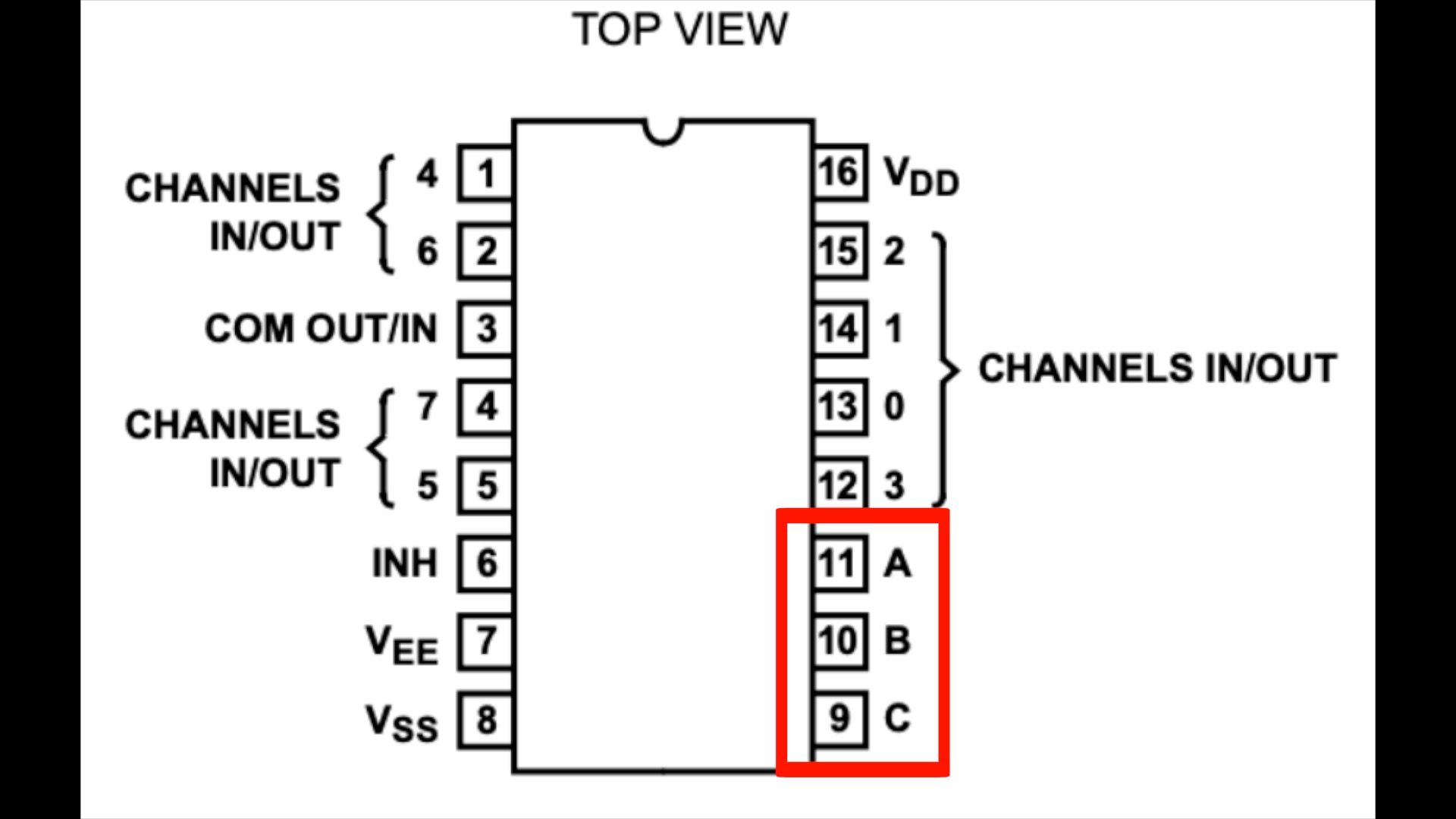
These pins will help us give order to the multiple inputs (maximum of 8 sensor data) coming into a single stream (Daisy’s ADC).
It works by sending digital outs from Daisy to these pins!!
From digital out pins, Daisy can output either a 0 (low) or 1 (high).

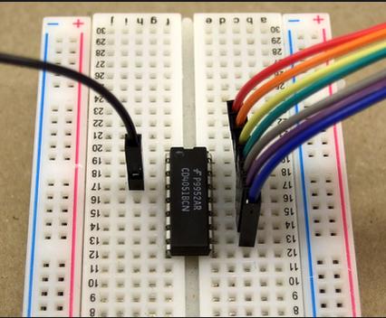
Let’s connect Daisy’s digital pin 0 (D0) to multiplexer’s pin 11 (S0). Then, Daisy’s pin D1 to multiplexer’s pin 10 (S1). Finally, Daisy’s D2 to multiplexer’s pin 9 (S2). Note: any pin with the label ‘D’ can be used as a Digital GPIO.

While at it, connect 3.3 volt to multiplexer’s VDD input (pin 16). And also ground pins 6, 7, and 8 together like this.

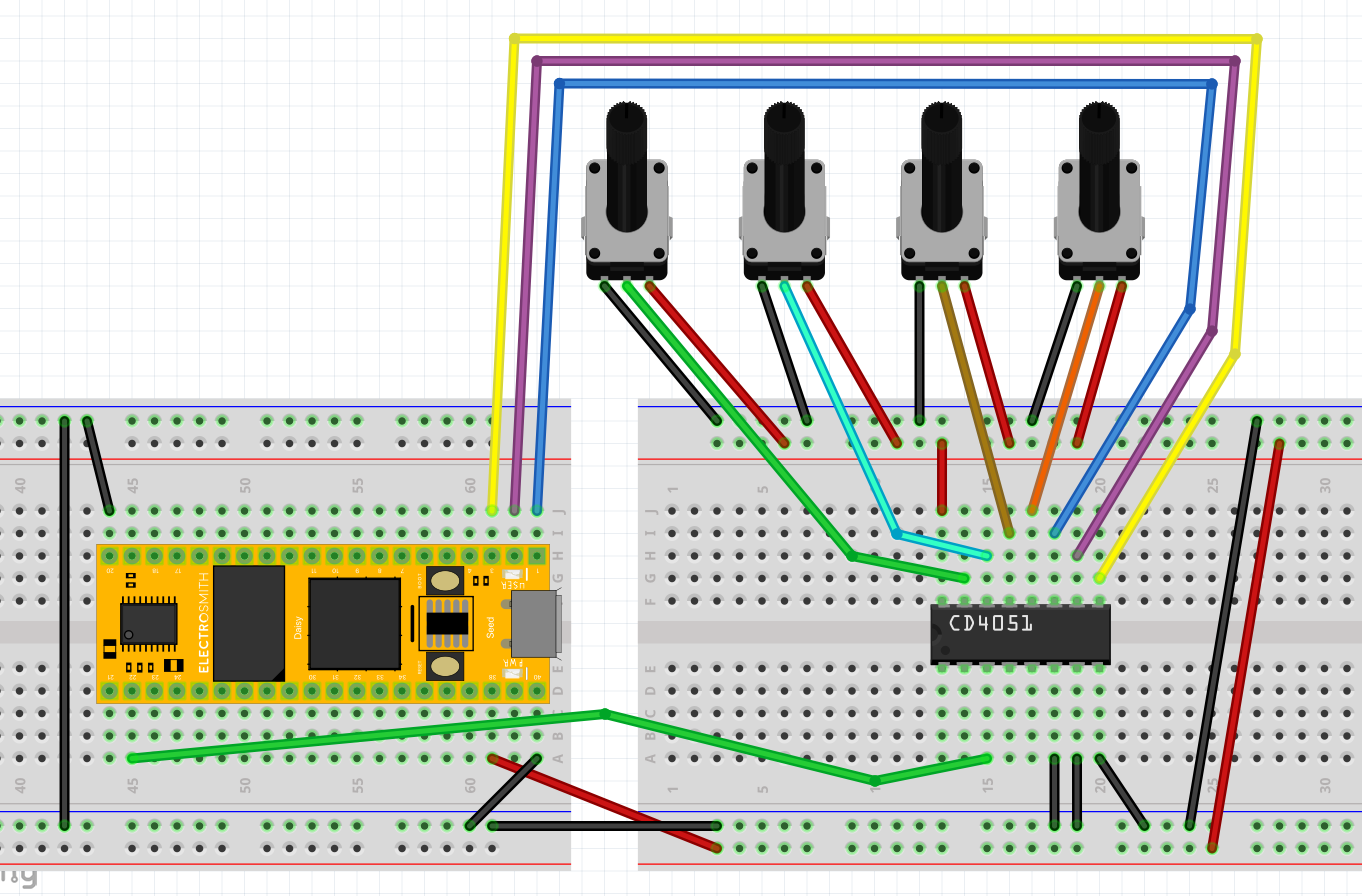
Well, look at that!! We actually finished hooking up Daisy to the multiplexer!

But, we still need to understand what these select pins are.

Let’s think of doors :door:

Again, we’ll start with 4 inputs for now.

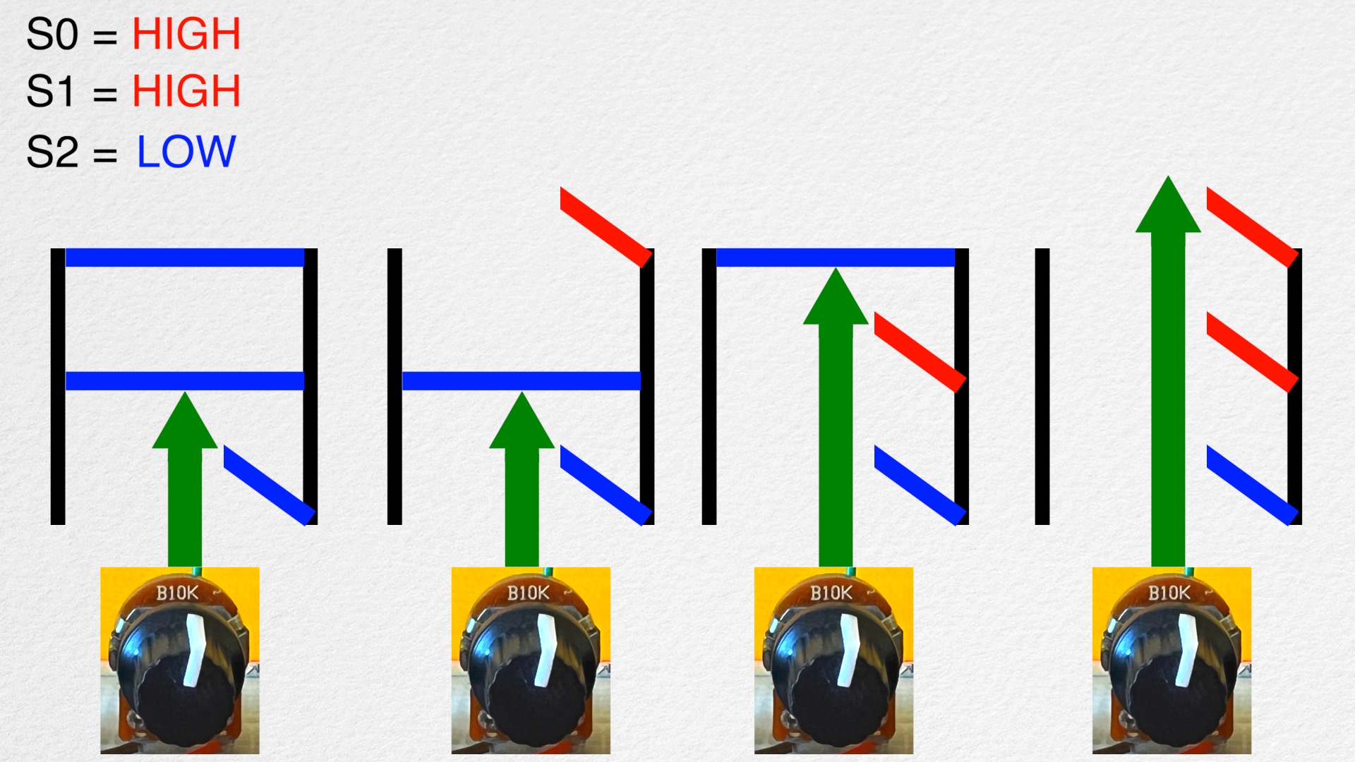
Each multiplexer inputs have 3 different combination of “doors” or “gates”. And a door opens when a matching “key” (digital outs from Daisy’s digital pins) is given. What the heck is this analogy?

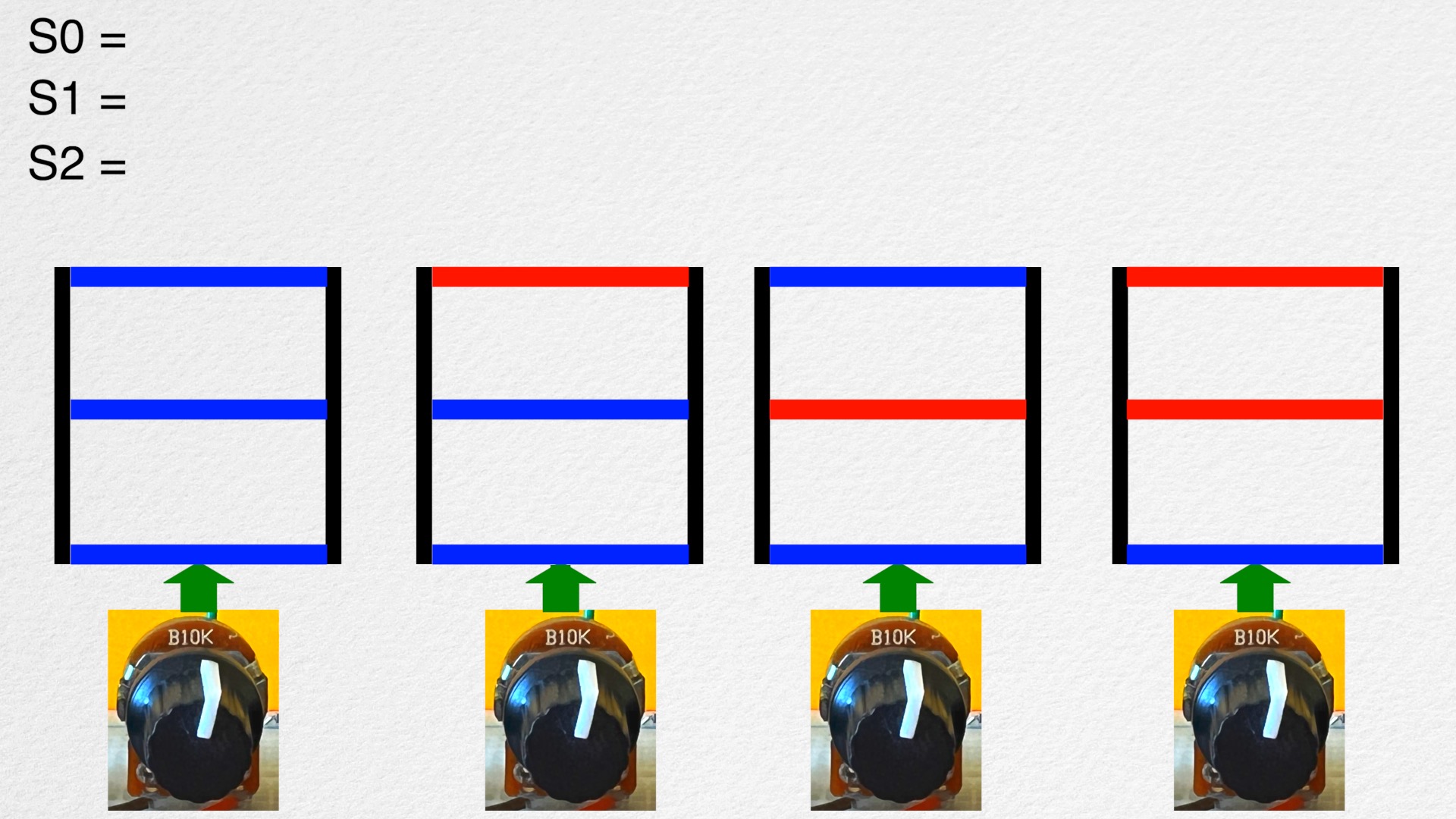
Color blue is “digital out LOW or 0” and red is “digital out HIGH or 1”. The first potentiometer on the left is connected to input 0 of the multiplexer. And the next potentiometer to the right is connected to input 1 of the multiplexer and so on…

Let’s take a look at an example.

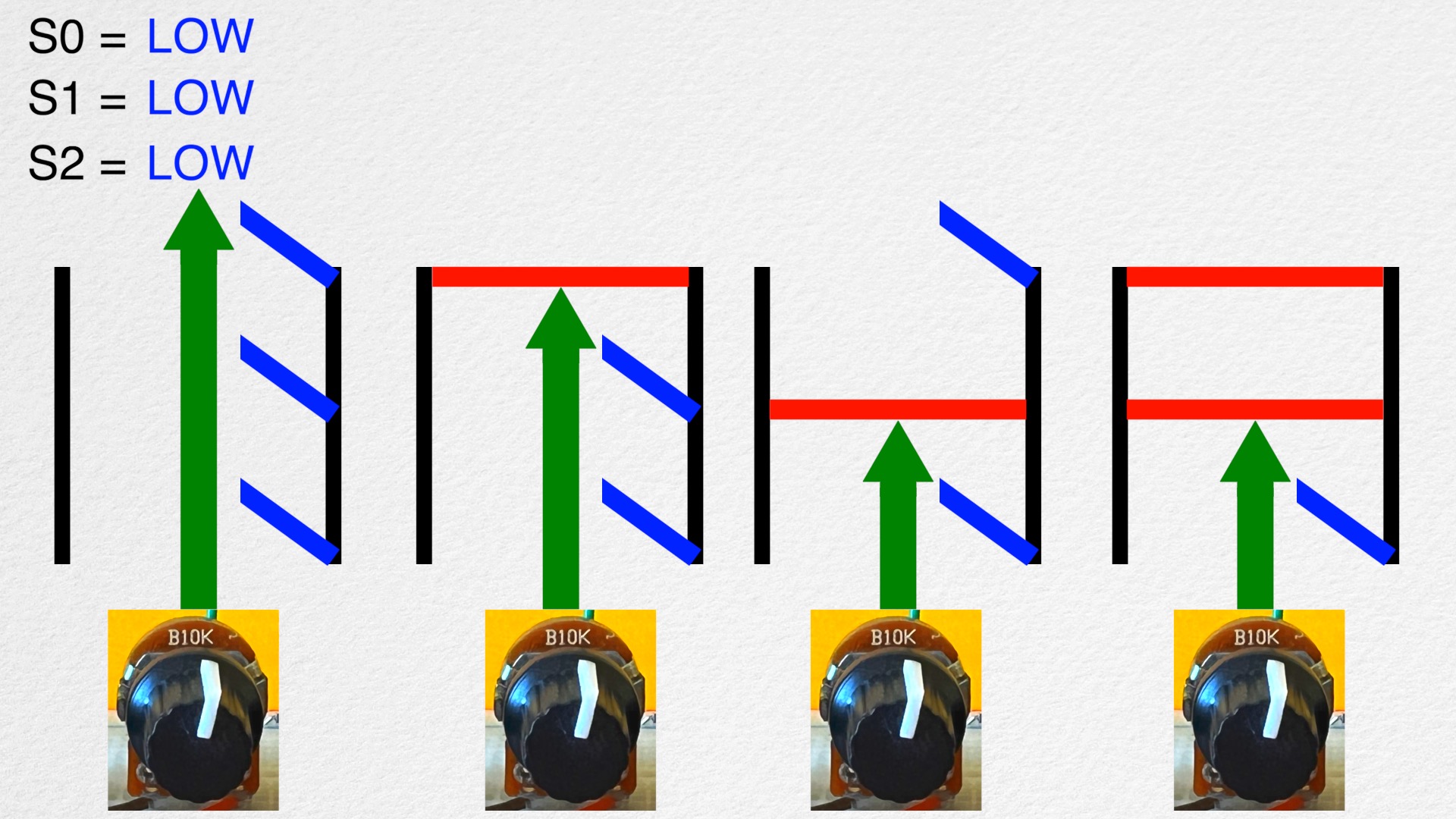
For S0 = low, S1 = low, and S2 = low, all 3 doors for input 0 will open. For all the other inputs, at least one door is closed, so the data cannot go through; it is gated off!

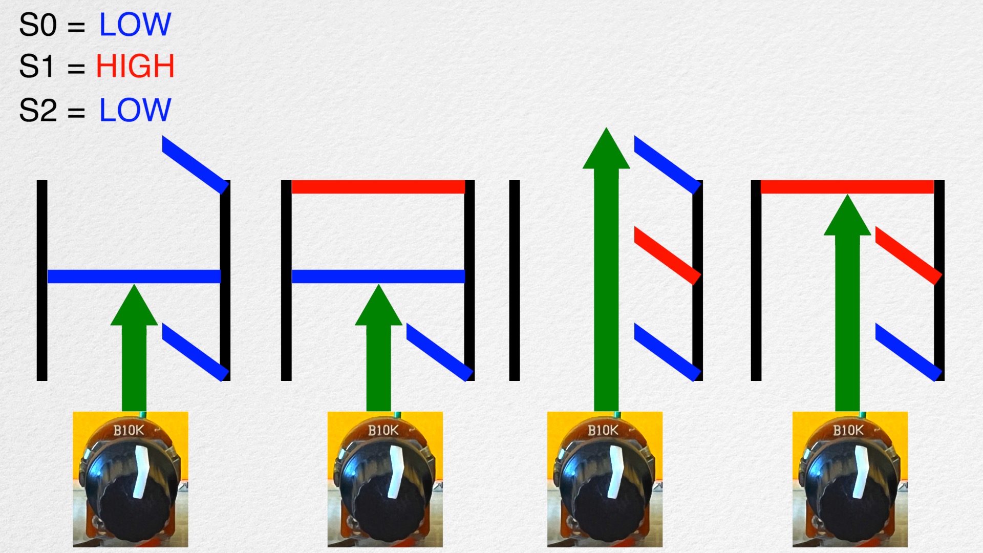
For S0 = high, S1 = low, and S2 = low, all 3 doors for input 1 will be opened.

And so on…

SO! Multiplexer works by selecting which input on the multiplexer can go through one at a time. And this input is selected by sending different combination of the digital outputs to the selector pins. Let’s take a closer look with a code!

Code (Arduino IDE) :keyboard:
Here’s the whole code for 8 inputs

#include "DaisyDuino.h"

#define analogPin0 A0 //ADC 0 
#define pinS2 2 //Pin D2 
#define pinS1 1 //Pin D1
#define pinS0 0 //Pin D0

void setup()
{
  Serial.begin(9600);

  //Set pins D0, D1, and D2 as digital outs
  pinMode(pinS2, OUTPUT);
  pinMode(pinS1, OUTPUT);
  pinMode(pinS0, OUTPUT);
}

void loop()
{
  
  //Only reading input 0 of the multiplexer 
  digitalWrite(pinS2, LOW);
  digitalWrite(pinS1, LOW);
  digitalWrite(pinS0, LOW);   
  Serial.print(analogRead(analogPin0));
  Serial.print("  "); 

  //Only reading input 1 of the multiplexer 
  digitalWrite(pinS2, LOW);
  digitalWrite(pinS1, LOW);
  digitalWrite(pinS0, HIGH);
  Serial.print(analogRead(analogPin0));
  Serial.print("  "); 

  //Only reading input 2 of the multiplexer 
  digitalWrite(pinS2, LOW);
  digitalWrite(pinS1, HIGH);
  digitalWrite(pinS0, LOW);
  Serial.print(analogRead(analogPin0));
  Serial.print("  "); 

  //Only reading input 3 of the multiplexer 
  digitalWrite(pinS2, LOW);
  digitalWrite(pinS1, HIGH);
  digitalWrite(pinS0, HIGH);
  Serial.print(analogRead(analogPin0));
  Serial.print("  "); 

  //Only reading input 4 of the multiplexer 
  digitalWrite(pinS2, HIGH);
  digitalWrite(pinS1, LOW);
  digitalWrite(pinS0, LOW);
  Serial.print(analogRead(analogPin0));
  Serial.print("  "); 

  //Only reading input 5 of the multiplexer 
  digitalWrite(pinS2, HIGH);
  digitalWrite(pinS1, LOW);
  digitalWrite(pinS0, HIGH);
  Serial.print(analogRead(analogPin0));
  Serial.print("  "); 

  //Only reading input 6 of the multiplexer 
  digitalWrite(pinS2, HIGH);
  digitalWrite(pinS1, HIGH);
  digitalWrite(pinS0, LOW);
  Serial.print(analogRead(analogPin0));
  Serial.print("  "); 

  //Only reading input 7 of the multiplexer 
  digitalWrite(pinS2, HIGH);
  digitalWrite(pinS1, HIGH);
  digitalWrite(pinS0, HIGH);
  Serial.println(analogRead(analogPin0)); 

  delay(50);

}

We can set pins D0, D1, and D3 as digital outs by using the pinMode() function like this.

  //Set pins D0, D1, and D2 as digital outs
  pinMode(pinS2, OUTPUT);
  pinMode(pinS1, OUTPUT);
  pinMode(pinS0, OUTPUT);

By setting all three digital pins to “LOW”, the analogRead() will exclusively be reading the data from multiplexer’s input 0. The data is then displayed using Serial.print().

  //Only reading input 0 of the multiplexer 
  digitalWrite(pinS2, LOW);
  digitalWrite(pinS1, LOW);
  digitalWrite(pinS0, LOW);   
  Serial.print(analogRead(analogPin0));
  Serial.print("  ");

Here’s input 0 of the multiplexer being displayed in Arduino IDE’s Serial Monitor. I should mention that the first knob on the left is connected to input 0 of the multiplexer. Then, the knob next to it on the right is connected to input 1 of the multiplexer and so on…

4051_0

Notice how twisting the second knob does not affect the displayed output?

To only read multiplexer’s input 1, set the digital pins to a combination of S2 = LOW, S1 = LOW, and S0 = HIGH.

  //Only reading input 1 of the multiplexer 
  digitalWrite(pinS2, LOW);
  digitalWrite(pinS1, LOW);
  digitalWrite(pinS0, HIGH);
  Serial.print(analogRead(analogPin0));
  Serial.print("  ");

4051_1
This time, twisting the first knob does not affect the displayed output

And I believe you get the idea for analyzing the rest of the code!
Let’s use 4 knobs all at once! Again, keep in mind that only 1 ADC is being used right now!!

4051_2

The inputs are being read one after the other almost simultaneously, which results in this expansion of ADC inputs!
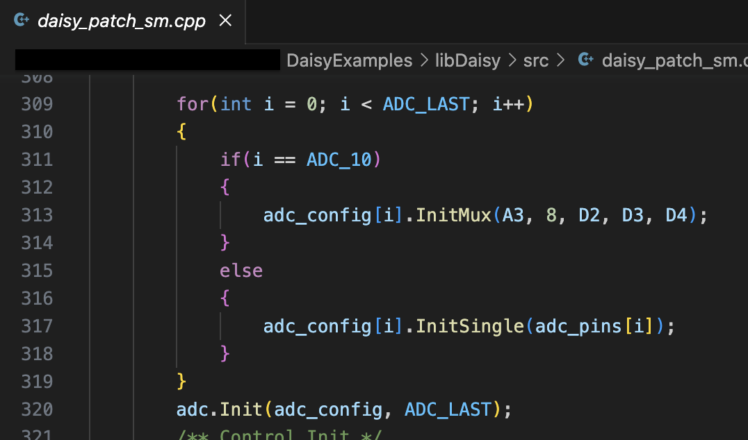
Code (C++) :keyboard:
There is a multiplexer function in libDaisy that we can use in C++. Here’s a code that utilizes it!

/** Example of using a CD4051 multiplexor to expand the ADC inputs */
#include "daisy_seed.h"

/** This prevents us from having to type "daisy::" in front of a lot of things. */
using namespace daisy;

/** Global Hardware access */
DaisySeed hw;

int main(void)
{
    /** Initialize our hardware */
    hw.Init();

    /** Configure the ADC
     * 
     *  One channel configured for 8 inputs via CD4051 mux. 
     * 
     */
    AdcChannelConfig adc_cfg;
    adc_cfg.InitMux(seed::A0, 8, seed::D0, seed::D1, seed::D2); 

    /** Initialize the ADC with our configuration */
    hw.adc.Init(&adc_cfg, 1);

    /** Start the ADC conversions in the background */
    hw.adc.Start();

    /** Startup the USB Serial port */
    hw.StartLog();

    /** Infinite Loop */
    while(1)
    {
        /** Print the values via Serial every 250ms 
         *  Values will be 0 when inputs are 0V
         *  Values will be 65536 when inputs are 3v3
         */
        System::Delay(250); 
        
        hw.Print("Input 1: %d", hw.adc.GetMux(0, 0)); 
        hw.Print("  ");

        hw.Print("Input 2: %d", hw.adc.GetMux(0, 1)); 
        hw.Print("  ");

        hw.Print("Input 3: %d", hw.adc.GetMux(0, 2));  
        hw.Print("  ");

        hw.Print("Input 4: %d", hw.adc.GetMux(0, 3)); 
        hw.Print("  ");

        hw.Print("Input 5: %d", hw.adc.GetMux(0, 4));  
        hw.Print("  ");

        hw.Print("Input 6: %d", hw.adc.GetMux(0, 5)); 
        hw.Print("  ");

        hw.Print("Input 7: %d", hw.adc.GetMux(0, 6));  
        hw.Print("  ");

        hw.PrintLine("Input 8: %d", hw.adc.GetMux(0, 7));   
    }
}

We initialize using adc_cfg.InitMux().

adc_cfg.InitMux(seed::A0, 8, seed::D0, seed::D1, seed::D2); 

First argument is Daisy’s ADC pin. Second argument is how many multiplexer inputs we’re using. If you put 4, you may need to ground the third select pin. Rest of the arguments are for Daisy’s digital out pins. If you put 4 for the 2nd argument, you only need to put two pins.

Use the GetMux() function to read one multiplexer input at a time. Notice the second argument corresponding to the multiplexer input pins.

hw.Print("Input 1: %d", hw.adc.GetMux(0, 0));

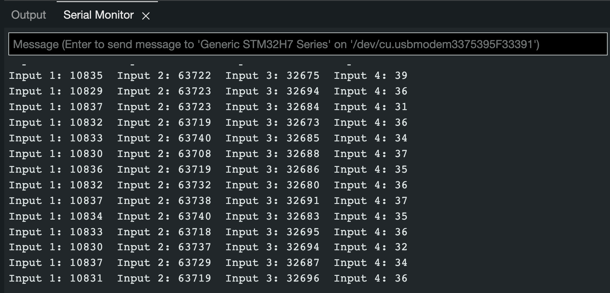
Let’s see if this works! Here’s what the serial monitor should look like. I’m using Arduino IDE’s Serial Monitor and only printing out 4 potentiometer data at once.
The values will be 0 when inputs are 0V and 65536 when inputs are 3v3.

What’s Next? :seedling:
Hopefully this tutorial was helpful enough for you to get started!!

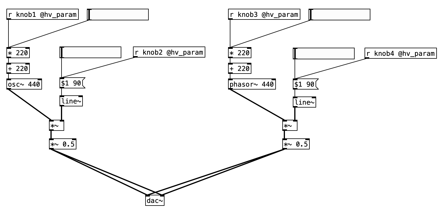
Mapping these expanded input data to synth parameters is going to be a fun next step!

Adding more multiplexer is another step that you could take!
I believe we can use the same digital pins on Daisy for newly added mutiplexers.
As for the code, this should be straightforward to do in Arduino IDE.

And for C++, you can reference here to get an idea of how to add more Mux functions.

Finally for Arduino IDE, there are bunch of multiplexer codes online, so I recommend checking them out for optimization (making the code succinct/clean)!

Have fun!!
Please feel free to share if you end up using a multiplexer for your next project!! And if you have experience using multiplexer, please let us know about any tips that’ll be helpful!! Thanks!!

Credits/references:
1
2
First photo

18 Likes

really appreciate this tutorial

1 Like

Can you perhaps also show what adding such a multiplexer to a board.json file would look like?

1 Like

I would love to do a follow up to this tutorial for pd2dsy and oopsy~ eventually for sure!

In the meantime, here are the steps for anyone curious to try it out before I can:
-Include 3 digital outputs and 1 adc in the .json file.
-In the patcher, change the combination of digital outputs in sequence while reading the analog input

4 Likes

With the current json implemenations of pd2dsy, and the update staged for release on oopsy you can do the following, which is copied from the daisy field.json file:

"parents":
  "pot_mux": {
    "component": "CD4051",
    "mux_count": 8, // the number of pots connected
    "pin": {
      "adc": 16,  // the ADC input pin
      "sel0": 21, // The SEL0 digital output pin
      "sel1": 20, // The SEL1 digital output pin
      "sel2": 19  // The SEL2 digital output pin
    }
  }
},
"components": {
  "knob1": {
    "component": "CD4051AnalogControl",
    "index": 0, // which analog input pin on the CD4051 to read
    "parent": "pot_mux"
  },
  "knob2": {
    "component": "CD4051AnalogControl",
    "index": 3, // which analog input pin on the CD4051 to read
    "parent": "pot_mux"
  }
},

edit: updated to be more complete (using parents and components relationship).

3 Likes

I’m having difficulty implementing this example on the Patch SM. As far as I can tell, it looks like I would only need to change the hardware and the the pins for the example to work on the Patch SM. However, I’m getting a crash when my code gets to hw.adc.Init(&adc_cfg, 1);.

I’m attempting to use pin D9 as my COM OUT/IN and pins D6 and D7 as my selector pins. D9 is labeled as ADC_11 and D6 and D7 are both shown as Digital GPIO in the Patch SM pinout so I think this configuration should work?

Here’s my full code:

/** Example of using a CD4051 multiplexor to expand the ADC inputs */
#include "daisy_patch_sm.h"

/** This prevents us from having to type "daisy::" in front of a lot of things. */
using namespace daisy;
using namespace patch_sm;

/** Global Hardware access */
DaisyPatchSM hw;

int main(void)
{
    /** Initialize our hardware */
    hw.Init();

        /** Startup the USB Serial port */
    hw.StartLog(true);
    hw.PrintLine("Log Started");

    /** Configure the ADC
     * 
     *  One channel configured for 8 inputs via CD4051 mux. 
     * 
     */
    AdcChannelConfig adc_cfg;

    adc_cfg.InitMux(hw.GetPin(DaisyPatchSM::PinBank::D, 9), 4, hw.GetPin(DaisyPatchSM::PinBank::D, 5), hw.GetPin(DaisyPatchSM::PinBank::D, 6)); 

    /** Initialize the ADC with our configuration */
    hw.adc.Init(&adc_cfg, 1);

    /** Start the ADC conversions in the background */
    hw.adc.Start();

    /** Infinite Loop */
    while(1)
    {
        /** Print the values via Serial every 250ms 
         *  Values will be 0 when inputs are 0V
         *  Values will be 65536 when inputs are 3v3
         */
        System::Delay(250); 
        hw.Print("Input 1: %d   ", hw.adc.GetMux(0, 0)); 
        hw.Print("Input 2: %d   ", hw.adc.GetMux(0, 1)); 
        hw.Print("Input 3: %d   ", hw.adc.GetMux(0, 2));  
        hw.Print("Input 4: %d   ", hw.adc.GetMux(0, 3)); 
        hw.PrintLine("");

    }
}

For my adc config I’ve also tried:

adc_cfg.InitMux(DaisyPatchSM::D9, 4, DaisyPatchSM::D5, DaisyPatchSM::D6);

Is there something I’m missing? I see AdcHandle is an available class on the Patch SM so not sure where I’m going wrong with this example.

If I remember correctly, you may have to ground the S2 pin even if it’s unneeded (you only need to switch around the 2 selector pins for 4 total inputs). I think that’s why, in this tutorial, I connected a digital pin to it even though I’m only using 4 potentiometers. So, I believe you need to either connect that pin to ground or add another digital pin for the third selector pin (and also configure it in code).

And this thread could be a helpful reference to you as well: MUX on Patch SM.

Thanks, but would having the S2 pin ungrounded cause my Patch SM to crash when calling hw.adc.Init(&adc_cfg, 1) ? That’s what seems to be happening to me.

Unfortunately I won’t be able to test again until tomorrow or Tuesday, but I’ll report back here with the results.

For sure, it shouldn’t crash it, I don’t think.
Regardless, give all those a try and keep me posted :slight_smile:

@Takumi_Ogata I tried testing again today, this time without the MUX code and just initialising the ADC. I am still getting a crash at hw.adc.Init(adc_cfg, 1);

This is my code:

/** Example of initializing multiple ADC inputs */
#include "daisy_patch_sm.h"
/** This prevents us from having to type "daisy::" in front of a lot of things. */
using namespace daisy;
using namespace patch_sm;
/** Global Hardware access */
DaisyPatchSM hw;
int main(void)
{
   /** Initialize our hardware */
   hw.Init();
    hw.StartLog(true);
    hw.PrintLine("Log Started");
   /** Configure the ADC
    *
    *  Three CV inputs (-5V to 5V -> 3V3 to 0V)
    *  A0, A6, and A2
    *
    *  This example was made for the Daisy Seed2 DFM, but the pins can be swapped for other hardware.
    */
   AdcChannelConfig adc_cfg[1];
   adc_cfg[0].InitSingle(DaisyPatchSM::A2);
   hw.PrintLine("after init single");

   /** Initialize the ADC with our configuration */
    hw.adc.Init(adc_cfg, 1);
    hw.PrintLine("after adc init");

   /** Start the ADC conversions in the background */
   hw.adc.Start();
   hw.PrintLine("after adc start");

   /** Startup the USB Serial port */
   /** Infinite Loop */
   while(1)
   {
       /** Print the values via Serial every 250ms
        *  Values will be 0 when inputs are 0V
        *  Values will be 65536 when inputs are 3v3
        *
        *  Based on the CV input circuit this means that
        *  Values will be 0 when input is 5V
        *  Values will be ~32768 when input is ~0V
        *  Values will be 65536 when input is -5V
        */
       System::Delay(250);
       int val_0 = hw.adc.Get(0); 
// OR float val_0 = hw.adc.GetFloat(0); to get vals // from 0 to 1
       hw.PrintLine("Input 1: %d", val_0);
   }
}

Hey zyxy398!

Ok, I see why it crashed.
The Init function for the Daisy Patch SM inits and starts the adc. So you could try to stop the adc right after calling hw.Init().
There’s no deinit function unfortunately.

It could be a good idea to for me to make a Patch SM version of the multiplexer example code (especially since we may make a video tutorial in the near future).

Hey, I just tried this and no more crash! Except that all the other adc and cv inputs no longer worked after that. I figured out this was because the new adc_cfg i was initialising the adc with only had a single value, the mux. I’d have to manually configure the 11 other adc pins if I wanted to use them. So in the end I do have it working, but my big question is, Is there a better way to use adc with the patch sm than to manually configure all the adc pins?

Hi Stains!

I’m sorry for the delay in response. I double checked with the team and this code that you posted on Discord seems like the simplest way to handle it actually.

Ah, but that requires a modification to the libDaisy itself, meaning I can’t easily commit this change to my own repo. I can live with it for now! Is there plans for a nicer way to configure MUX with the the patch SM that doesn’t involve modifying libDaisy or reinitialising all ADC pins?

It should be possible to pull that code out of libdaisy for cleanliness.

Either way, thank you for bringing this to our attention. We’ll have more discussion about it especially when we create a more proper tutorial for using mux :slight_smile:

1 Like

Thank you for such a nice tutorial explaining multiplexer!
As I understood for pd2dsy you do all the code in PD and in custom json file you define analog and digital pins?
How do you add digital outs in custom json file for pin 0,1 and 3?
Could you show a simple PD patch for 1 or 2 knobs coming from the multiplexer?
Thank you

1 Like

Sure!

Here’s the json file:

{
  "name": "mux",
  "som": "seed",
  "parents": {
    "pot_mux": {
      "component": "CD4051",
      "mux_count": 8,
      "pin": {
        "adc": 15,
        "sel0": 0,
        "sel1": 1,
        "sel2": 2
      }
    }
  },
  "components": {
    "knob1": {
      "component": "CD4051AnalogControl",
      "index": 0,
      "parent": "pot_mux"
    },
    "knob2": {
      "component": "CD4051AnalogControl",
      "index": 3,
      "parent": "pot_mux"
    },
    "knob3": {
      "component": "CD4051AnalogControl",
      "index": 1,
      "parent": "pot_mux"
    },
    "knob4": {
      "component": "CD4051AnalogControl",
      "index": 4,
      "parent": "pot_mux"
    },
    "knob5": {
      "component": "CD4051AnalogControl",
      "index": 2,
      "parent": "pot_mux"
    },
    "knob6": {
      "component": "CD4051AnalogControl",
      "index": 5,
      "parent": "pot_mux"
    },
    "knob7": {
      "component": "CD4051AnalogControl",
      "index": 6,
      "parent": "pot_mux"
    },
    "knob8": {
      "component": "CD4051AnalogControl",
      "index": 7,
      "parent": "pot_mux"
    }
  },
  "aliases": {
    "knob": "knob1",
    "ctrl": "knob1",
    "ctrl1": "knob1",
    "ctrl2": "knob2",
    "ctrl3": "knob3",
    "ctrl4": "knob4",
    "ctrl5": "knob5",
    "ctrl6": "knob6",
    "ctrl7": "knob7",
    "ctrl8": "knob8"
  }
}

And your patch can be something like this. The [line~] is for smoothing out the sensor data, which is especially crucial for amplitude.

1 Like

This is just great Takumi, thank you very much!

What about using some other multiplexer? Do you just change the name in the json file or this works only with the CD4051?

What are these aliases for in the json file?

As long as it has 3 selector pins like the CD4051, you should be able to keep things the same in the json file.

Hi @Takumi_Ogata , thanks for the great tutorial. I managed to change it to work with the Pod.

One noob question, if you don’t mind:

Both the pots and the multiplexer chip are powered via 3V3 Digital. Aren’t the pots supposed to be powered to 3V3 Analog and the CD4051 via 3V3 Digital?

Thanks