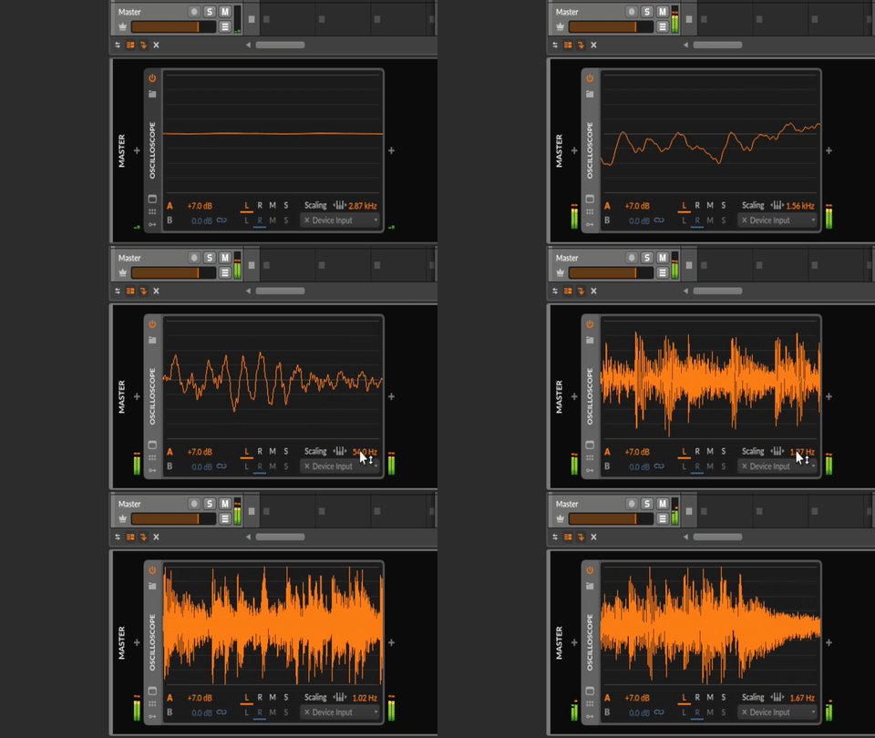
Is an Audio In OLED oscilloscope possible?

Apologies for a very newbie question. I’ve been poking around the examples/forums and doing some experimentation on my Daisy Seed the past two days but I’ve realized I’m a bit in over my head trying to make this a reality.

With the Daisy Seed I thought I might be able to drive a small I2C 128x32 OLED screen to draw an oscilloscope visualizer of incoming audio. After all, I saw a video of an Oopsy example doing just that with Max/MSP on the Daisy Patch.

I’d hoped I could maybe cobble this together in Arduino using the U8G2 library, but I’m having trouble figuring out how to utilize the callback routine’s InputBuffer for this - if that’s even a possibility (I’m beginning to think it isn’t). I thought the answer may lie in using ADC instead of audio in, but I’m a bit confused because I don’t see any DaisyDuino examples that use ADC, so I don’t really know how to start? (Possible I’m misidentifying what arduino ADC examples look like).

I realize this is an odd use-case for the Daisy since I’m not even trying to do any DSP, I’d figured the embedded audio would make this simpler than trying to do something like this from scratch with a teensy or something :sweat_smile:.

A) If you can envision a way to let a Daisy Seed drive an I2C OLED to be an audio-in oscilloscope (preferably in Arduino but open to any answers) how would you start?
or B) Is this a completely foolish idea to pursue because this is not an intended use-case?

Thanks in advance! Sorry for an open-ended newbie question!

Maybe this could be used as a starting point?

I checked this out before, it’s cool that it has the code for updating the oled, however all it’s doing is running two identical oscillators, one that’s operating in the audio callback and the other for driving the oscilloscope. It’s doing nothing with an input signal which is what I’m stuck on.

I’m wondering if it’s possible to, say, write values from the InputBuffer to a variable that can get accessed in loop() or main() in some code that would be updating the oled display, or if there’s some other way to do this, or if it isn’t possible.

You’d need a ring buffer to collect the data (either raw, or processed). Then, you just need to draw the contents of the buffer. I guess the tricky part would be to map samples to pixels.

1 Like

UPDATE: When you’re trying to experiment with stuff and you’re looking for an expected outcome, it’s probably a good idea to correctly write your code. Still open to suggestions but I’ve gotten past the barrier I was behind!

For those curious, my problem was basically I was missing the line

  num_channels = hw.num_channels;

in the Bypass example! Silly me! :sweat_smile:

Yeah, as @brbrr says, a ring buffer is the way to go.

Pseudo-code

buffer[SIZE];
ptr = 0;
audiocallback()
buffer[ptr] = audio_in;
ptr++ % SIZE;

main()
…setup code

while (true)
    draw pixels where Y = (buffer[i] + 1)/2 * (height of OLED in pixels)

I don’t know if this is any help or if I am just stating the obvious (or too simple). BTW I think there is a Daisy ringbuffer implementation in some file in libdaisy.

1 Like

Thanks @StaffanMelin and @brbrr! Truth be told this is the first I’m learning about ring buffers but y’all are totally right that’s the way to go! I see the ringbuffer class in libdaisy :open_mouth: Think there’s an example that uses it anywhere? I think I mostly get how it works but would like to see an example just in case.

Hmm it doesn’t seem like the daisy ringbuffer is a part of DaisyDuino? I suppose I’ll just build it from scratch or use a library

Update: Something is happening

When I first ran into problems with this project, and with my limited experience with microcontrollers, I didn’t think I would even get this far. I’m thrilled that this even at least looks like an oscilloscope, but I’ve kinda reached my limit of knowledge on how to troubleshoot its jumpiness and the tearing.

Here’s my code:

#include <CircularBuffer.h>

#include <AudioClass.h>
#include <DaisyDSP.h>
#include <DaisyDuino.h>
#include <hal_conf_extra.h>

#include <U8g2lib.h>

#ifdef U8X8_HAVE_HW_SPI
#include <SPI.h>
#endif
#ifdef U8X8_HAVE_HW_I2C
#include <Wire.h>
#endif

U8G2_SSD1306_128X32_UNIVISION_F_HW_I2C u8g2(U8G2_R0, /* reset=*/ U8X8_PIN_NONE, /* clock=*/ SCL, /* data=*/ SDA);   // pin remapping with ESP8266 HW I2C

DaisyHardware hw;

CircularBuffer<float, 526> buf;

size_t num_channels;
//float val; 
int displayWidth, displayHeight;

void MyCallback(float **in, float **out, size_t size) {
  for (size_t i = 0; i < size; i++) {
    for (size_t chn = 0; chn < num_channels; chn++) {
      out[chn][i] = in[chn][i]; //bypass audio
      buf.push(in[0][i];); 
    }
  }
}

void setup(void) {
  float samplerate;
  //  Serial.begin();
  hw = DAISY.init(DAISY_SEED, AUDIO_SR_48K);
  num_channels = hw.num_channels;
  samplerate = DAISY.get_samplerate();
  displayWidth = 128;
  displayHeight = 32;
  u8g2.begin();
  DAISY.begin(MyCallback);
}

void loop(void) {
  u8g2.clearBuffer();
  for (int i = 0; i < displayWidth; i++) {
    int smpl = constrain(((buf.shift() + 1) / 2 * displayHeight), 0, 128); //hard clip the oscilloscope
    u8g2.drawPixel(i, smpl);
  }
  u8g2.sendBuffer();
  delay(40);
}

The CircularBuffer size is kind of arbitrary as I tweaked it many times to see how it affected the visuals. I feel like at least one part of many of my problem has to do with the discrepancy between the refresh rate of the Callback vs the refresh rate of Loop vs the refresh rate of the OLED?

Is there a way to access the InputBuffer outside of the callback? I feel like I’d rather write the audio_in to the buffer within loop() instead of MyCallback? I don’t know if that would make it better or worse.

I’m using this library so I don’t have to write my own ringbuffer :stuck_out_tongue:

2 Likes

@donutshoes, great, you are really moving forward!

The ringbuffer is what lets you access the audio_in outside of the audiocallback (ACB).

Now you have to synchronize the drawing of the OLED. You are filling the buffer at 48K, so the distance between each value is 1/48k s. How fast is the OLED? If it is “slow” you might have to skip values from the buffer.

In eaither case, I think I would decide upon an update speed of the OLED. Say like 1000 Hz. Then you have a small timing loop in main() where you every 1/1000 sec take 48 values and take the mean of them and use as the Y value.

You can use:

/** \return a uint32_t of microseconds within the internal timer. */
    static uint32_t GetUs();

Looking forward to your next update!

1 Like

Ok so this is definitely performing better aside from an obvious bug that I cannot identify. As you can see, the oscilloscope works for a portion of the OLED screen and then seemingly uses a single y value for the rest of it.

Here’s the code:

#include <CircularBuffer.h>

#include <AudioClass.h>
#include <DaisyDSP.h>
#include <DaisyDuino.h>
#include <hal_conf_extra.h>

#include <U8g2lib.h>

#ifdef U8X8_HAVE_HW_SPI
#include <SPI.h>
#endif
#ifdef U8X8_HAVE_HW_I2C
#include <Wire.h>
#endif

U8G2_SSD1306_128X32_UNIVISION_F_HW_I2C u8g2(U8G2_R0, /* reset=*/ U8X8_PIN_NONE, /* clock=*/ SCL, /* data=*/ SDA);   // pin remapping with ESP8266 HW I2C

DaisyHardware hw;

CircularBuffer<float, 48> buf;

const unsigned long period = 1000; //period of time to perform an OLED update, in microseconds
const unsigned long countPeriod = 48; //averaging period, aka the number of incoming values to average
unsigned long previousTime, count, previousCount; //pieces of timer code
float avg; //average of samples
int lastSmpl; //used in OLED draw

size_t num_channels;
int displayWidth, displayHeight;

void MyCallback(float **in, float **out, size_t size) {
  for (size_t i = 0; i < size; i++) {
    for (size_t chn = 0; chn < num_channels; chn++) {
      out[chn][i] = in[chn][i]; //bypass audio
      avg += in[0][i]; //continuously add up incoming values
      if (count - previousCount >= countPeriod) { //after 48 callback loops
        avg /= countPeriod; //average the added values
        buf.push(avg*2); //push to CircularBuffer, amplified
        avg = 0; //reset to zero
        previousCount = count; //reset timer
      }
      count++;
    }
  }
}

void setup(void) {
  float samplerate;
  //  Serial.begin();
  hw = DAISY.init(DAISY_SEED, AUDIO_SR_48K);
  num_channels = hw.num_channels;
  samplerate = DAISY.get_samplerate();
  displayWidth = 128;
  displayHeight = 32;
  lastSmpl = 16; //keeps edge pixel in one place
  u8g2.begin();
  DAISY.begin(MyCallback);
}

void loop(void) {
  unsigned long currentTime = micros();
  if (currentTime - previousTime >= period) { //when the period has elapsed
    lastSmpl = 16; //keeps edge pixel in one place
    u8g2.clearBuffer();
    for (int i = 0; i < displayWidth; i++) { //for every pixel the display is wide
      updateOLED(i, buf.shift()); //shift() means get first value in buffer and remove from buffer, pass i and that value into updateOLED()
    }
    u8g2.sendBuffer();
    previousTime = currentTime; //reset timer
  }
}

void updateOLED(int x, float val) {
  float y = (val + 1) / 2 * displayHeight; //map the incoming averaged value from -1, 1 to 0, displayHeight
  float currentSmpl = constrain(y, 0, displayHeight); //create currentSmpl value from y and constrain to displayHeight
  u8g2.drawLine(x, lastSmpl, x+1, currentSmpl); //draw a line from last sample to current sample
  lastSmpl = currentSmpl; //reassign last sample as the current one
}

The OLED I’m using is 128x32
Again I am using the CircularBuffer library I linked above
Bear in mind some value types might be weird as I was testing some very large numbers to see how it reacted :sweat_smile:

Here are some observations while messing around with some values.
A) The CircularBuffer size correlates to a delay between when the working part of the oscilloscope moves and when the straight line moves. The larger the buffer is, the longer the delay.
B) The working portion of the oscilloscope lengthens the smaller the Averaging Period is, with some kind of limit. Bringing the Averaging Period down to 2 lengthens the working portion of the oscilloscope to a little less than half the OLED screen.

I’m guessing this is still some kind of sync issue between the callback loop and the OLED framerate? I tried messing around with the period of OLED updates but nothing significant seemed to change that I could tell.

1 Like

Cool!

I think you can simplify this. Sorry, can’t test this as I don’t have an oled and I am sitting on my balcony with a “wintercoffee” :slight_smile:

Instead of using the circular buffer from the lib. Create your own array of floats.

#define DISPLAY_WIDTH 128 // or whatever it is
#define DISPLAY_HEIGHT 48 // or whatever
#define CHUNK 48
float buf[DISPLAY_WIDTH];
uint8_t readptr, writeptr;
bool draw;

void acb()
{
we read CHUNK bytes
average them
save to buf[writeptr]
writeptr += 1 % DISPLAY_WIDTH
draw = true;
}

setup()
{
readptr = 0;
writeptr = 0;
draw = false;
}

void main()
{
if (draw)
{
y = buf[readptr] * DISPLAY_HEIGHT;
x = readptr;
// draw on oled
readptr += 1 % DISPLAY_WIDTH;
w = false;
}

}

Also I think that the acb is called for 48 values at a time, so you really don’t need a counter for this.

I hope this is not confusing.

1 Like

EDIT: FIGURED IT OUT
.
.
.
I mostly understand your code here, but I’m confused about a couple things.

“we read CHUNK bytes” - in a for loop? or some other way?

#define DISPLAY_WIDTH 128;
#define CHUNK 48;
void acb()
{
  for (size_t i = 0; i < size; i++) {
    for (size_t chn = 0; chn < num_channels; chn++) {
      for (int j = 0; j < CHUNK; j++){
      avg += in[0][i];
      }
     avg /= CHUNK;
     buf[writeptr] = avg;
     writeptr += 1 % DISPLAY_WIDTH;
     avg = 0;
  }
 }
}

like that?

“acb is called for 48 values at a time” - how so? is it delivered as an array? something else?

(also, I’m sure it was obvious but I’ve only been dealing with one channel’s input so far, will experiment with summing L+R once I have it working)

EDIT: FIGURED IT OUT
.
.
.
Oh wait, are you saying the averaging and writing to the buffer happen at the end of the acb? Outside of the two for loops?

Oop I understand now, thanks! :sweat_smile:

1 Like

Well hot damn, that’s an oscilloscope!!! Thanks so much for all your help with this, I learned a lot, both in coding fundamentals and how the Daisy works.

Here’s the final code I’m running:

#include <AudioClass.h>
#include <DaisyDSP.h>
#include <DaisyDuino.h>
#include <hal_conf_extra.h>

#include <U8g2lib.h>

#ifdef U8X8_HAVE_HW_SPI
#include <SPI.h>
#endif
#ifdef U8X8_HAVE_HW_I2C
#include <Wire.h>
#endif

#define DISPLAY_WIDTH 128
#define DISPLAY_HEIGHT 32
#define CHUNK 6

U8G2_SSD1306_128X32_UNIVISION_F_HW_I2C u8g2(U8G2_R0, /* reset=*/ U8X8_PIN_NONE, /* clock=*/ SCL, /* data=*/ SDA);   // pin remapping with ESP8266 HW I2C

DaisyHardware hw;

const unsigned long period = 1000; //period of time to perform an OLED update, in microseconds
unsigned long previousTime, currentTime;
float avg; //average of samples
int lastSmpl; //used in OLED draw

size_t num_channels;

float buf[DISPLAY_WIDTH];
uint8_t readptr, writeptr;
bool draw;

void AudioCallback(float **in, float **out, size_t size) {
  for (size_t i = 0; i < size; i++) {
    for (size_t chn = 0; chn < num_channels; chn++) {
      out[chn][i] = in[chn][i]; //bypass audio
      avg += in[chn][i]; //continuously add up incoming values
    }
  }
  avg /= CHUNK;
  buf[writeptr] = avg * 2;
  writeptr++;
  writeptr %= DISPLAY_WIDTH;
  avg = 0; //reset to zero
  draw = true;
}

void setup(void) {
  float samplerate;
  //  Serial.begin();
  hw = DAISY.init(DAISY_SEED, AUDIO_SR_48K);
  num_channels = hw.num_channels;
  samplerate = DAISY.get_samplerate();
  readptr = 0;
  writeptr = 0;
  lastSmpl = 16;
  draw = false;
  u8g2.begin();
  DAISY.SetAudioBlockSize(CHUNK);
  DAISY.begin(AudioCallback);
}

void loop(void) {
  unsigned long currentTime = micros();
  if (draw) {
    if (currentTime - previousTime >= period) {
      u8g2.clearBuffer();
      for (int i = 0; i < DISPLAY_WIDTH; i++) {
        float y = buf[readptr];
        int x = readptr;
        updateOLED(x, y);
        readptr += 1 % DISPLAY_WIDTH;
      }
      u8g2.sendBuffer();
      draw = false;
      previousTime = currentTime;
    }
  }
}

void updateOLED(int x, float val) {
  float y = (val + 1) / 2 * DISPLAY_HEIGHT; //map the incoming averaged value from -1, 1 to 0, displayHeight
  float currentSmpl = constrain(y, 0, DISPLAY_HEIGHT-1); //create currentSmpl value from y and constrain to displayHeight
  u8g2.drawLine(x, lastSmpl, x + 1, currentSmpl); //draw a line from last sample to current sample
  lastSmpl = currentSmpl; //reassign last sample as the current one
}

When I first ran this with a CHUNK size of 48, the values appeared to be updating quite slowly. Decreasing the CHUNK size sped it up. I don’t know if there’s a different way I could be doing this? I’m not really questioning it since it’s working :sweat_smile:

My next step is to somehow figure out how to implement this functionality, would love to have a pot I can turn to alter the scale. I’m somewhat confident (potentially overconfident) in my ability to figure it out, but any suggestions are welcome (I don’t mean to exploit folks’ generous brainstorming on here)

ezgif.com-gif-maker

4 Likes

That is frigging great! I am sure a lot of people will find a use for this so thanks for sharing!

I even started a project in openFrameworks to be able to help you better, but the frameworks are too different to be of any use.

Anyways, I was only the backseat driver you did all the work. And it looks awesome.

For working with pots, maybe you can find something interesting in my OscPocketD project? It has some connected pots and read and act on the values.

1 Like

I don’t think this does what you think it does.

You’re right, it doesn’t. Thanks.

Here’s the final mark 1 build!

Surprised myself by figuring out how to implement horizontal scaling, other knob is vertical scaling.

There’s one last thing that I can’t figure out though. If there isn’t a stereo plug plugged into the output, and if it doesn’t then lead to a stereo input, then the pots behave as if there’s grounding issues. AGND and DGND are bridged, and the audio jacks and OLED screen work fine regardless. I’d like it to be fully functioning even without needing to use the output.

Here’s the code:

#include <CircularBuffer.h>

#include <AudioClass.h>
#include <DaisyDSP.h>
#include <DaisyDuino.h>
#include <hal_conf_extra.h>

#include <U8g2lib.h>

#ifdef U8X8_HAVE_HW_SPI
#include <SPI.h>
#endif
#ifdef U8X8_HAVE_HW_I2C
#include <Wire.h>
#endif

#define DISPLAY_WIDTH 128
#define DISPLAY_HEIGHT 32
#define CHUNK 6

U8G2_SSD1306_128X32_UNIVISION_F_HW_I2C u8g2(U8G2_R0, /* reset=*/ U8X8_PIN_NONE, /* clock=*/ SCL, /* data=*/ SDA);   // pin remapping with ESP8266 HW I2C

DaisyHardware hw;
size_t num_channels;

const unsigned long period = 16777; //period of time to perform an OLED update, in microseconds
unsigned long previousTime, currentTime;
uint64_t currentCount, previousCount;
uint8_t hKnob, vKnob;
float addIn, avg; //average of samples
int lastSmpl; //used in OLED draw
int avgPeriod = 6; //number of 6 sample 'chunks' to average, larger period means slower horizontal scaling
int vScale = 2; //vertical scaling amount
int previousValue;
CircularBuffer<float, DISPLAY_WIDTH> buf;
bool draw;

void AudioCallback(float **in, float **out, size_t size) {
  for (size_t i = 0; i < size; i++) {
    for (size_t chn = 0; chn < num_channels; chn++) {
      out[chn][i] = in[chn][i]; //bypass audio
      addIn += in[chn][i]; //continuously add up incoming values
    }
  }
  currentCount++;
  if (currentCount - previousCount >= avgPeriod) {
    avg += addIn;
    avg /= CHUNK * avgPeriod;
    buf.push(avg * vScale);
    if (buf.isFull()) {
      buf.shift();
    }
    avg = 0;
    addIn = 0;
    draw = true;
    previousCount = currentCount;
  }

}

void setup(void) {
  float samplerate;
//  Serial.begin();
  hw = DAISY.init(DAISY_SEED, AUDIO_SR_48K);
  num_channels = hw.num_channels;
  samplerate = DAISY.get_samplerate();
  lastSmpl = 16;
  draw = false;
  hKnob = A2;
  vKnob = A0;
  pinMode(hKnob, INPUT);
  pinMode(vKnob, INPUT);
  u8g2.begin();
  DAISY.SetAudioBlockSize(CHUNK);
  DAISY.begin(AudioCallback);
}

void loop(void) {
  unsigned long currentTime = micros();
  if (draw) {
    if (currentTime - previousTime >= period) {
      u8g2.clearBuffer();
      for (int i = DISPLAY_WIDTH; i > 0; i--) {
        float y = buf[i];
        int x = i;
        updateOLED(x, y);
      }
      u8g2.sendBuffer();
      draw = false;
      previousTime = currentTime;
    }
  }

  //Stabilize potentiometers, assign values to horizontal and vertical scaling
  int h = smooth(hKnob);
  avgPeriod = map(h, 0, 1023, 1, 256); //
  int v = smooth(vKnob);
  vScale = map(v, 0, 1023, 2, 32);
}

void updateOLED(int x, float val) {
  float y = (val + 1) / 2 * DISPLAY_HEIGHT; //map the incoming averaged value from -1, 1 to 0, displayHeight
  float currentSmpl = constrain(y, 0, DISPLAY_HEIGHT - 1); //create currentSmpl value from y and constrain to displayHeight
  u8g2.drawLine(x, lastSmpl, x + 1, currentSmpl); //draw a line from last sample to current sample
  lastSmpl = currentSmpl; //reassign last sample as the current one
}

int smooth(uint8_t pot) {
  int result;
  int newValue = 0;
  const int numReadings = 48;
  for (int i = 0; i < numReadings; i++) {
    newValue += analogRead(pot);
  }
  newValue /= numReadings;

  //additional stabilization? I don't know if it's doing much
  if (abs(previousValue - newValue) > 2) {
    result = newValue;
    previousValue = newValue;
  } else {
    result = previousValue;
  }
  return result;
}
4 Likes