The kxmx_bluemchen - An open source, 4hp, Daisy based Eurorack module

Thanks for the information! Would be great if support was officially added to libDaisy (soon :wink:).

Nice to learn about the design updates! I am also interested in a DIY kit (or maybe more). Referring to someone’s earlier suggestion, would you consider ordering the PCBs with assembled SMT parts?

Great to hear this! :rocket:

I am interested in obtaining a PCB only or kit. Do you have a rough estimate how much those would be respectively?

I’m waiting on a PCBA order from JLCPCB. When they arrive, I’ll need to find a good way to functionally test the populated boards, I have no idea how this is typically done, so I’ll have to figure that out.

Parallel to that, I’ve been trying to source enough through hole parts for a handful of kits and built modules. Unfortunately some of the parts are pretty difficult to come by.

Once I get everything together, I’ll build a couple of modules and document the process for a build guide. At that point I’ll post a link to a registration form where interested parties can order what they are interested in. And I’ll do my best to fulfill things in a first come first serve manner.

Regarding prices… I’m aiming for the following:

  • 99€ / USD $119 - DIY kit (through hole soldering) without Daisy Seed
  • 139€ / USD $159 - DIY kit (through hole soldering) including Daisy Seed
  • 199€ / USD $229 - Built Module

…but these are subject to change depending on how much time I end up needing to invest. At the end of the day I have a family, and a job, and my time is awfully precious. This is also why I don’t see any reason to sell just PCBs - it’s not really worth my time. If you really want PCBs without parts, just get them fabbed yourself - everything in this project is open source. It will be cheaper anyhow.

What I could imagine is someone designing their own front PCB/panel, built off my back PCB. In this case the PCBA assembled back board might be interesting to just purchase. I’d be open to selling them in this case, as it might make someone’s life a little easier.

Thanks to the folks who have expressed interest. It keeps me motivated to move forward with this project.

6 Likes

Nice to hear it’s moving forward.

Regarding the testing. Have you seen Émilies video on R&D of new modules?
IIRC there are a few nice tricks on testing.

1 Like

I saw that video when it first came out, and just watched it again. Inspirational for sure, even if my goals are most definitely not to join the crowded ranks of Eurorack module manufacturers.

While the best-practices outlined int the video are a great, I’m looking for answers to much simpler questions, like how do I make reliable electrical contact to the un-soldered header pin holes? I know there are spring loaded pogo pins for a bed-of-nails like thing, but then I need a jig and some sort of clamp - seems pretty complicated for just 25 boards. I’d be fine with some type of friction connector (like a banana jack) which fits in header pin holes.

I’ll figure it out.

Hi everyone,

I know it’s been a while, but I have been actively working on this project, and now it’s time for an update.

SO…

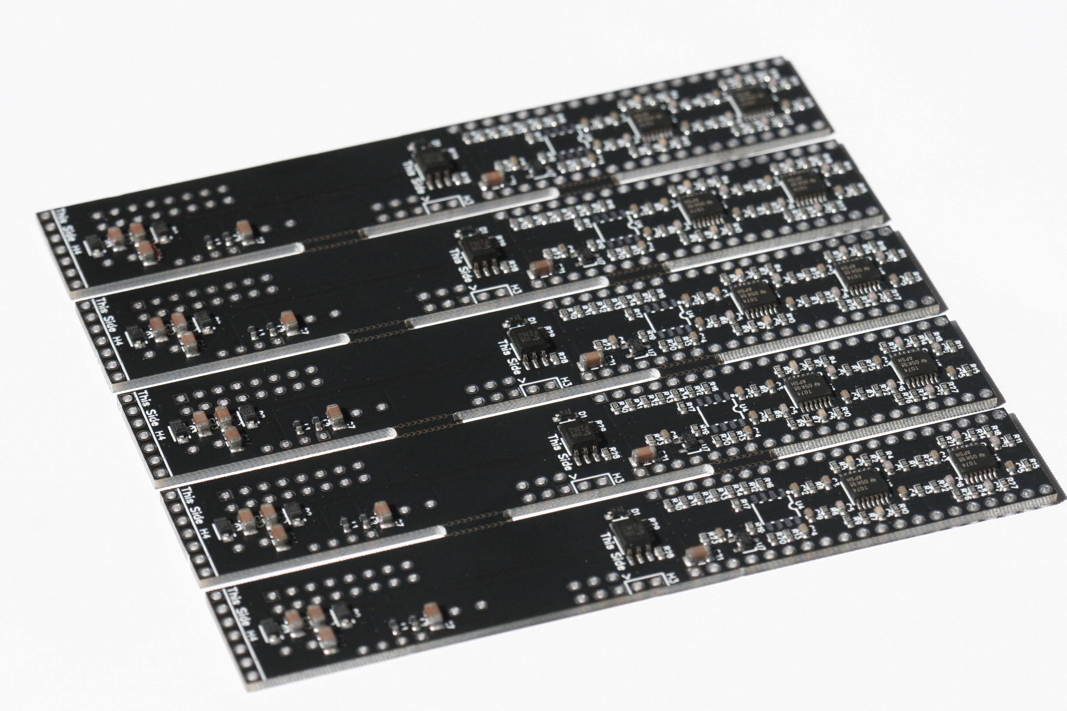
I tried out the PCBA service from JLCPCB, and other than the shipping taking over four weeks (I think the Evergiven incident played a role in that), it went off without a hitch. I had a batch of 25 made (5x5 panelized) and they turned out pretty good:

Unfortunately the MCP6002s were out of stock, so I needed to hand solder them. Oh, and splitting panelized boards is a messy pain in the ass. Also, I still haven’t found a good way to test the assembled boards, but I’ve built three modules so far, so at least 12% of the boards are proven good .

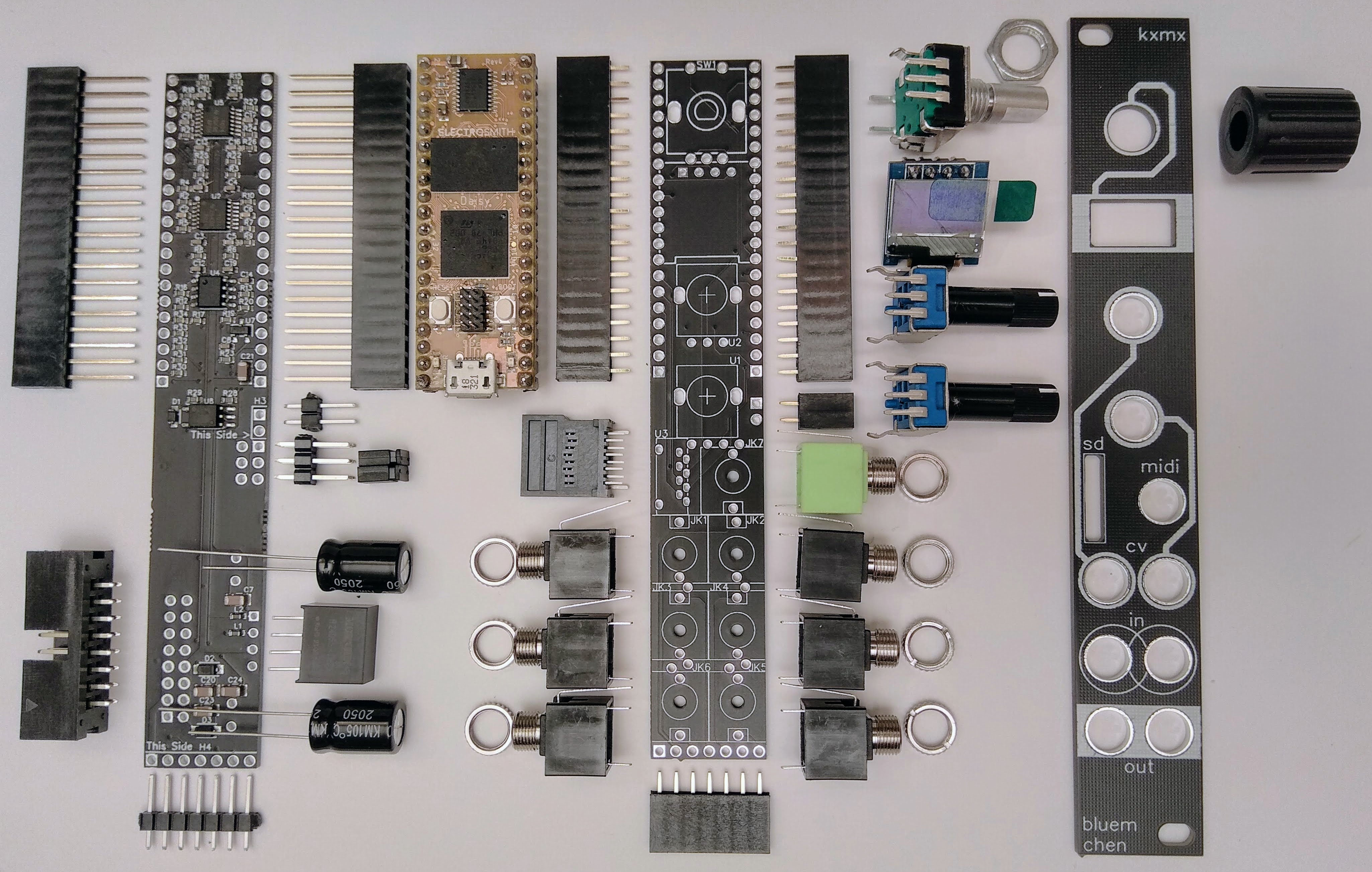
While assembling those modules, I documented and photographed the process, and made an assembly guide for the DIY kits I’m making available

So now that I have all the orders for parts out and I’m waiting for them to trickle in, I guess it’s as good a time as any to start taking requests. I’ve put up a website, and a registration form for those of you genuinely interested in buying a DIY kit or a module. I’m selling 10 DIY kits and 10 modules and will be handling requests first-come-first-serve. There’s a very good chance I won’t be making any more after this, so grab one now if you want one.

On the software side of things, this module doesn’t need much. Since my pull-request was merged into libDaisy, it can be used as-is, and there are no more workarounds necessary. My repo provides a basic implementation for this hardware, and an example program for testing the features. I’m also working with @grrrwaaa on getting support for this module integrated into oopsy, which might be interesting for some folks.

That’s about it. Thanks to everyone who provided feedback here, it helped keep me motivated and see this little project through.

p.s. Just for fun, I added the module to ModularGrid.

8 Likes

AMAZING

@grrrwaaa can we get this added to [oopsy~] ???

I’m working on it. Progress is slow because I’ve been busy, but it’s coming.

1 Like

In the meantime, “YES!” Absolutely sign me up for at least one, if not two.
IMHO this is a form factor that should be a permanent piece of the Daisy ecosystem.

Thanks so much for all the work this must have been, really looking forward to building a few!

Just a couple of questions about the BOM, there is no listing for the value of the alpha pots, are they just 100k linear pots for the CV control?

Also, the vertical SD holder seems to be out of stock most places, will the module work without populating it and I can just install it later?

Cool, happy to hear you’re building your own!

It’s just a voltage divider, an value will do as long as it’s linear.

Yes, the module will work fine without the MicroSD socket. Indeed the PJS008U-3000-0 is one of the hardest parts to find. If you’re in the UK you can get them from Thonk, or in the EU, I found them reasonably priced in small quantities in the midiphy shop.

If you are planning to do a PCBA run, be aware that there is a critical mistake in the way EasyEDA panellized the design:

As you can see, the breakaway holes in the panel tabs go through a trace (CV 1). I’m in the process of repairing 20 of the 25 I ordered, and it’s a HUGE pain in the ass. I hope you didn’t already send out an order. If you’re hand soldering and had single boards fabbed, then the current design works fine.

3 Likes

Thanks for the quick response!

Great news on both fronts. I’m in Aus, so I’ll wait until Thonk have some knobs and pots I’m waiting on for another project.

I just got single boards, so hopefully shouldn’t have too many issues.

I’ll let you know how I get on!

My parts finally arrived and I’ve assembled a board. Audio I/O seems to be working, I don’t have pots for CV yet, so I’m guessing the CV ins wont work, and I’m currently trying to get the display working.

Are there any tricks to making the screen work?

I’m current trying to breadboad the Daisy and screen to ensure no bad soldering to confirm whether or not I have a useable OLED

The pots and CV ins are separate. I just made the panel look like they have an attenuverting relationship, but actually they don’t. I wanted access to as many params as possible.

Last week I found a regression in libDaisy that prevented the OLED from initializing. It has since been merged and I’ve updated my repo submodules to point at the fix ref. As long as you’re using the current HEAD of my kxmx_bluemchen repo, then there shouldn’t be any software issues.

Assuming you have a module like this one with built in pull-up resistors, The circuit is dead simple:

bluemchen_oled_detail

Check continuity on those traces to ensure your PCB is sound. There is not a lot to go wrong here hardware wise.

1 Like

Thank you so much for all your help.

The HEAD branch pointed me in the right direction, something is messed up with my build environment, but I had a clean install of everything on another pc and is working fine now.

Hey,
I think I checked all this on my build, the display is working with a simple Arduino sketch, I also followed the traces. When I look into the I2C Implementation in LibDaisy, i find that:

i2c_config.pin_config.scl = {DSY_GPIOB, 8};
i2c_config.pin_config.sda = {DSY_GPIOB, 9};

which are respectively Pin 9 & 10 of the Module…
On The Board SCL/SDA are wired to Pin 12&13 …

Am I getting sth wrong here?

Cheers, Bernd

No, they are pin 12 and 13 respectively, see here (count from the beginning of the array).

Maybe, maybe not. are you use a recent libDaisy? As I mentioned in an earlier post, there was a bug until last week.

Provide some more info and maybe I can help further.

Thanks for your quick answer :slight_smile: 
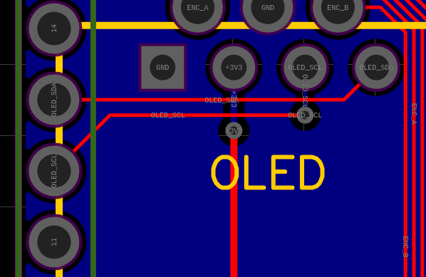
I’m using the latest Toolchain and cloned the HEAD from your Github repository (just did that freshly today) with the linked submodules. Also thanks for the clarification of the Pinout, now that make sense to me. I’m still lost why the OLED is not working… To sort out things softwarewise, could you provide us with a working / compiled hardware_test.bin to have a test reference for the hardwarebuild?

Would be much easier to ensure that the build works ok…

Thanks again for a great module :wink:
Cheers, Bernd

That is a good idea.

Here you go.

This bin is verified working on my modules. If it doesn’t work for you then we’ll have to investigate further.

Works like a charm! I’ll go over the toolchain again, lets see if it works with a fresh install. Is the exact Version of the ARM Toolchain any important? I took the latest (gcc-arm-none-eabi-10-2020-q4-major-x86_64-linux) and your recent Version from Github…

Thanks for the binary thou :slight_smile:

Cheers,
Bernd

1 Like