SSD1306 I2C OLED doesnt' work

Hi all!
Hi all! I am having trouble configuring my daisy seed board to work with an OLED I2c ssd1306 display. I looked at the OLED seed example and changed the configuration part as follows, but I couldn’t print anything on the screen:


#include <stdio.h>
#include <string.h>
#include "daisy_seed.h"
#include "dev/oled_ssd130x.h"

using namespace daisy;

using MyOledDisplay = OledDisplay<SSD130xI2c128x64Driver>;

DaisySeed     hw;
MyOledDisplay display;

int main(void)
{
    uint8_t message_idx;
    hw.Configure();
    hw.Init();

    /** Configure the Display */
    MyOledDisplay::Config disp_cfg;
    disp_cfg.driver_config.transport_config.i2c_address               = 0x78;
    disp_cfg.driver_config.transport_config.i2c_config.periph         = I2CHandle::Config::Peripheral::I2C_1;
    disp_cfg.driver_config.transport_config.i2c_config.speed          = I2CHandle::Config::Speed::I2C_100KHZ;
    disp_cfg.driver_config.transport_config.i2c_config.mode           = I2CHandle::Config::Mode::I2C_MASTER;
    disp_cfg.driver_config.transport_config.i2c_config.pin_config.scl = {DSY_GPIOB, 8};    disp_cfg.driver_config.transport_config.i2c_config.pin_config.sda = {DSY_GPIOB, 9};
    /** And Initialize */
    display.Init(disp_cfg);
    message_idx = 0;
    char strbuff[128];
    while(1)
    {
        System::Delay(500);
        switch(message_idx)
        {
            case 0: sprintf(strbuff, "Testing. . ."); break;
            case 1: sprintf(strbuff, "Daisy. . ."); break;
            case 2: sprintf(strbuff, "1. . ."); break;
            case 3: sprintf(strbuff, "2. . ."); break;
            case 4: sprintf(strbuff, "3. . ."); break;
            default: break;
        }
        message_idx = (message_idx + 1) % 5;
        display.Fill(true);
        display.SetCursor(0, 0);
        //display.DrawCircle(20, 20, 10, true);
        display.WriteString(strbuff, Font_11x18, false);
        display.Update();
    }
}

For the rest of the code, I left it unchanged. I also tried to change the speed to 400kHz and 1MHz but still couldn’t print anything. I also checked if the screen was broken but with an Arduino, it works perfectly.
Regarding connections:
-GND pin is connected to daisy DGND
-VCC to daisy 3V3 Digital
-SCL to daisy pin 12
-SDA to daisy pin 13
-Two 4k7 external resistors connect pin 12 and pin 13 to 3V3 Digital.
I also checked with DSO the SDA and SCL lines and I can clearly see activity there.
Do you have any idea? Thank you a lot to anyone who will answer me!

3 Likes

UPDATE:
I finally found the solution. I will write it here to avoid other people to experience the same situation.
The problem was that I was changing I2C_address to “0x78”, instead of leaving the default value of “0x3C”. I did that because 0x78 is the address written behind my OLED screen. I can’t understand why, but leaving the address to default 0x3C works fine.

4 Likes

Just found this and it’s really helped me out, cheers!

1 Like

Hey! I’ve been looking to add an OLED screen to my Daisy Seed and found this post. I can’t find much documentation on how to do this and I’m somewhat newish to all this so I was wondering if you could help point me in the right direction. There’s a lot already here that’s really helpful but is there some documentation for all of this that you could direct me to? Thanks!

1 Like

Hi @sknight. There is an “OLED” example for the seed platform. As far as I understood, you have to change the line using MyOledDisplay = OledDisplay<SSD130x4WireSpi128x64Driver>; by putting the type of display you are using (SPI/I2C and pixel format). You can see the options in the “oled_display.h” file. Then, you have to change the lines disp_cfg.driver_config.transport_config.pin_config.dc = hw.GetPin(9); disp_cfg.driver_config.transport_config.pin_config.reset = hw.GetPin(30); according to the pins you wish to use (pay attention that if you want to use I2C you have to configure different pins, not dc/reset, but scl/sda).
Hope I can help you :slight_smile: Let me know if you need further help!

Hi,

Hope it is OK that I revive this old topic. I’m struggling trying to get a DfRobot OLED display (Monochrome 0.91”128x32 I2C OLED Display SKU:DFR0648) to work with my Daisy Seed using I2C.

VCC is connected to 3V3Digital, GND to AGND and DGND, SCL to physical pin 12 on the Daisy and SDA to physical pin 13.

When I run the code below, random pixels are lit and nothing changes when I try to output different messages in a loop as in the Seed OLED example. I have also tried adding 4k7 resistors from 12 and 13 to 3V3 though it from the Daisy Seed schematics appears that they are already there.

Am I missing something? Any help is much appreciated!

#include "daisy_seed.h"
#include "daisysp.h"
#include "dev/oled_ssd130x.h"

using namespace daisy;
using namespace daisysp;

DaisySeed hw;

OledDisplay<SSD130xI2c128x32Driver> display;

std::string my_string = "Hello";
const char *char_array = my_string.c_str();

int main(void) {

	hw.Init();

	/** OLED display configuration */
	OledDisplay<SSD130xI2c128x32Driver>::Config display_config;

	display_config.driver_config.transport_config.i2c_address = 0x3C;
	display_config.driver_config.transport_config.i2c_config.periph = I2CHandle::Config::Peripheral::I2C_1;
	display_config.driver_config.transport_config.i2c_config.speed  = I2CHandle::Config::Speed::I2C_100KHZ;
	display_config.driver_config.transport_config.i2c_config.mode = I2CHandle::Config::Mode::I2C_MASTER;
 	display_config.driver_config.transport_config.i2c_config.pin_config.scl = {DSY_GPIOB, 8};
	display_config.driver_config.transport_config.i2c_config.pin_config.sda = {DSY_GPIOB, 9};

	//display_config.driver_config.transport_config.Defaults();
	display.Init(display_config);

	while(1) {
		display.Fill(true);
		display.SetCursor(0, 0);
		display.WriteString(char_array, Font_11x18, false);

		System::Delay(1000);
	}
}

Hi @tore,
honestly your code seems fine.
The only difference I can notice with respect to my code is that you are missing the display.Update() call.
Another thing you can try is to use directly a char buffer and including “string.h” as in the OLED example, instead of std::string.
Also, try to check if the cables you are using are not broken (sometimes it can happen :grin:)
Let me know if this solves your problem.

OMG. Adding display.Update() fixed it and I feel incredibly stupid. Thanks a lot Dox, for pointing this out! I’ll go hide in a corner now.

1 Like

BTW, if somebody else have the DfRobot 128x32 OLED and have trouble getting text written to 0,0 to align left, modifying the Update() method in oled_ssd130x.h as follows did the trick for me:

  void Update()
    {
        uint8_t i;
        uint8_t high_column_addr;
        /**
        switch(height)
        {
            case 32: high_column_addr = 0x12; break;

            default: high_column_addr = 0x10; break;
        }
        */
        // Modified to get correct offset
        high_column_addr = 0x10;
        for(i = 0; i < (height / 8); i++)
        {
            transport_.SendCommand(0xB0 + i);
            transport_.SendCommand(0x00);
            transport_.SendCommand(high_column_addr);
            transport_.SendData(&buffer_[width * i], width);
        }
    };

And no, I don’t really know what I am doing, but after having spent a long time comparing the init commands to those of other libraries (U8g2), this post spi - Horizontal offset with generic SSD1306 OLED display - Electrical Engineering Stack Exchange got me tinkering with the Update() method and it seems to work perfectly.

2 Likes

Can anybody confirm if this still works? I’m trying to get this working with the Adafruit 128x64 display and it powers on but the screen remains black. Same code and wiring setup as the OP (using the 0x3C address). Using Seed Rev4 board. Tested the OLED with an arduino and it works fine.

Any help is much appreciated!!

It does. Have you added the external pull-up resistors as well?

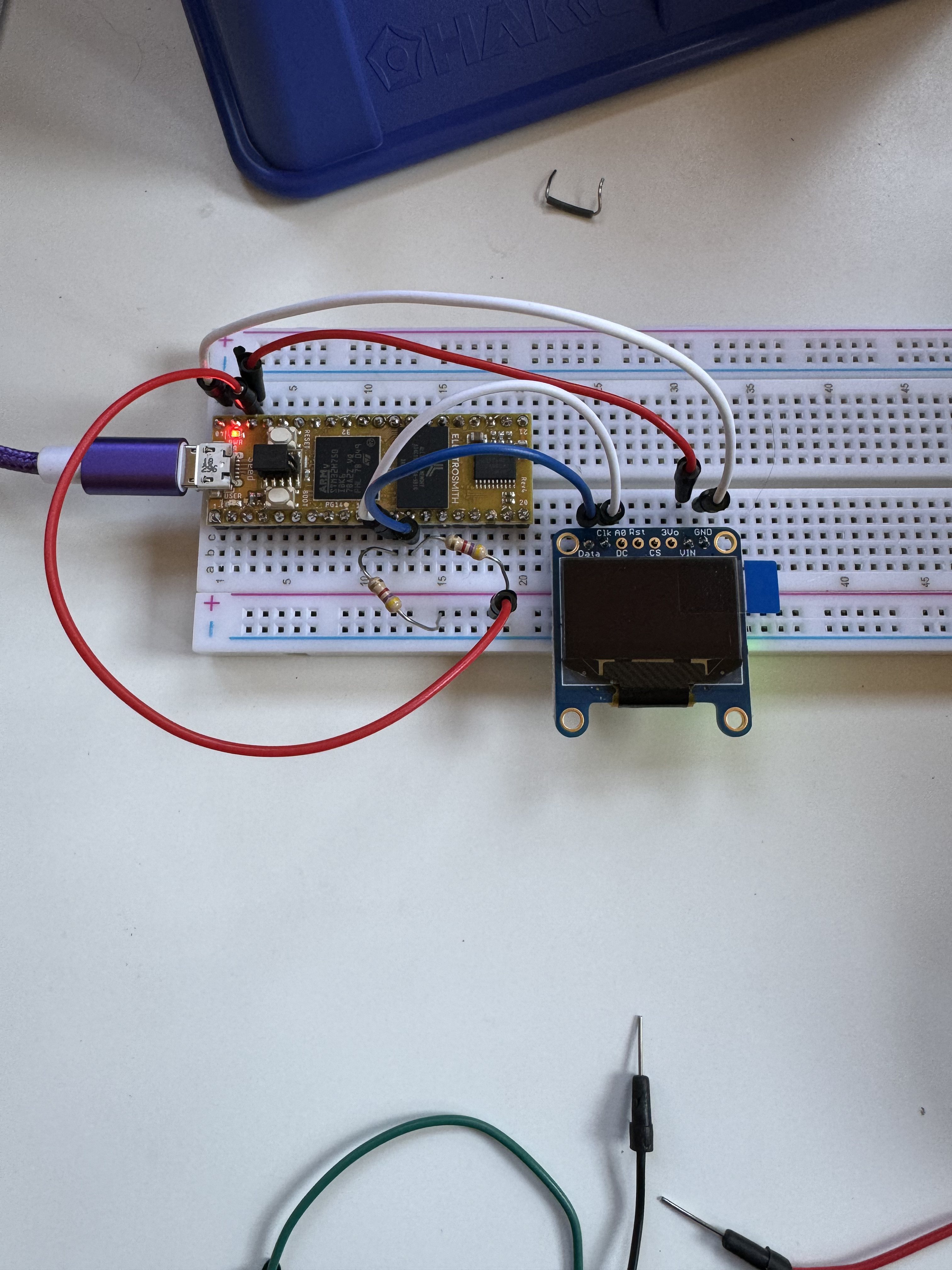
Thanks for the quick reply! Yes I’m using the 4.7k resistors. I’ve tried using the regular pins and the Stemma QT connection with the same result. Here’s a photo of the setup and the code I’m using.

#include <stdio.h>
#include <string.h>
#include "daisy_seed.h"
#include "dev/oled_ssd130x.h"

using namespace daisy;

using MyOledDisplay = OledDisplay<SSD130xI2c128x64Driver>;

DaisySeed     hw;
MyOledDisplay display;

int main(void)
{
    uint8_t message_idx;
    hw.Configure();
    hw.Init();

    /** Configure the Display */
    MyOledDisplay::Config disp_cfg;
    disp_cfg.driver_config.transport_config.i2c_address               = 0x3C;
    disp_cfg.driver_config.transport_config.i2c_config.periph         = I2CHandle::Config::Peripheral::I2C_1;
    disp_cfg.driver_config.transport_config.i2c_config.speed          = I2CHandle::Config::Speed::I2C_100KHZ;
    disp_cfg.driver_config.transport_config.i2c_config.mode           = I2CHandle::Config::Mode::I2C_MASTER;
    disp_cfg.driver_config.transport_config.i2c_config.pin_config.scl = {DSY_GPIOB, 8};    
    disp_cfg.driver_config.transport_config.i2c_config.pin_config.sda = {DSY_GPIOB, 9};
    //disp_cfg.driver_config.transport_config.i2c_config.pin_config.scl = hw.GetPin(11);    disp_cfg.driver_config.transport_config.i2c_config.pin_config.sda = hw.GetPin(12);;
    /** And Initialize */
    display.Init(disp_cfg);
    message_idx = 0;
    char strbuff[128];
    while(1)
    {
        System::Delay(500);
        /**/
        switch(message_idx)
        {
            case 0: sprintf(strbuff, "Testing. . ."); break;
            case 1: sprintf(strbuff, "Daisy. . ."); break;
            case 2: sprintf(strbuff, "1. . ."); break;
            case 3: sprintf(strbuff, "2. . ."); break;
            case 4: sprintf(strbuff, "3. . ."); break;
            default: break;
        }
        message_idx = (message_idx + 1) % 5;
        display.Fill(true);
        display.SetCursor(0, 0);
        //display.DrawCircle(20, 20, 10, true);
        display.WriteString(strbuff, Font_11x18, false);
        display.Update();
    }
}

You will also need to connect the two grounds together: pins 20 and 40

Why connect the two grounds? It isn’t mentioned anywhere in the I2C examples. I tried it anyway and saw no change.

This is the standard practice when prototyping with Daisy: 7. Troubleshooting · electro-smith/DaisyWiki Wiki · GitHub

more: Daisy Seed SimpleADC · Issue #33 · electro-smith/DaisyExamples · GitHub
page6: https://static1.squarespace.com/static/58d03fdc1b10e3bf442567b8/t/620a731d8d579c389a3f37dc/1644852002708/Daisy_Seed_datasheet.pdf

(I’m sure there is a better reference as to the “why”, but I can’t quickly find one)

Huh. Good to know! Thanks for the links.

This OLED should work when seed is only powered via USB, correct?

As far as I understand, there is a 3V3 regulator onboard, so they use the 5V input to the module with 5V and nonetheless connect to 3V3 logic level. Pullups 10k are included.
Wiring 128x64 OLEDs | Monochrome OLED Breakouts | Adafruit Learning System

Adafruit Learning System

Thanks for the reply! Are you suggesting I don’t need the external 4.7k resistors?

Yes.
I don’t know this module myself but had some look at the documents at Adafruit. I would measure Voltage at the 3V3 pad of the module against it’s GND pad. Sometimes these breadboards give insufficient contact and solder joints can give trouble too. Perhaps it is needed to supply 5V to the VIn pad of the module.

I powered the OLED with 5V and saw no change. The green LED on the back of the module lights up with 3.3v and 5v, but nothing happens on the screen.