Hi, I’m using the Daisy Seed in a mixed line out / euro rack out synth environment and I was thinking of ways to not overload the Daisy Seed’s analog inputs. I understand from the datasheet of the ad-converter that it can withstand 3.3 V + 0.6 V at max, so I was wondering whether 2 anti parallel zeners of 3.3 V would do the trick? Or are there other methods someone would recommend?
Yes that’s the simplest way. Two back to back zener or schottky diodes, a “clamp”.
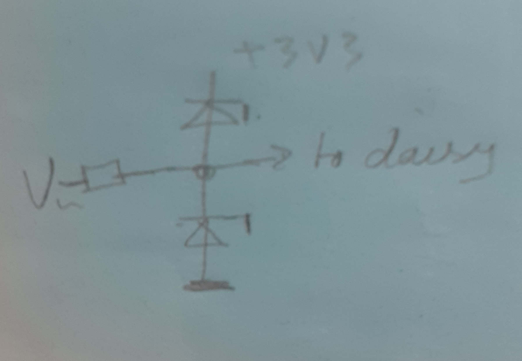
One diode to analog +3.3v the other to ground.
You could also place a non inverting unity gain OpAmp after the diodes. But it all depends on what you are in-putting in the first place and to which pin/type.
If you chose to add switches to GPIO inputs you can protect the inputs via a HC14 Schmitt trigger, this will also debounce
Yes that’s a standard way. But the resistor might not been needed as a current limiter.
Maybe a resistor value of 220 or 470 ohm if included
Here’s a video that might be of interest

1 Like
Thx for the reference!
Give that my input signal is audio, I gather the zener will distort the audio if it gets close to the zener voltage. So I might need a different solution.
Yes, the peaks of your audio will clip at the diode voltage rating.
Basically: If you put a pure sine wave in and increased the amplitude eventually it’ll clip and tend towards a square wave.
You might want to search for , ‘analog audio limiters’ or possibly ‘analog audio compressors’.
It can be a complex topic w.r.t slew rate, noise, impedance. etc etc
But you should be able to find some simple circuits that will suit your needs.
A basic attenuation circuit might work as well.
If you clamp at + /- 3.3v with the zeners then you are protecting your circuit/processor.
If a user sticks in +/- 5v then it’ll clip and distort, but at least you are protecting your circuit
Tell the user “don’t max out the input or else it’ll distort.”.
If you restrict your input this way and protect, you can always amplify on the output
1 Like
The usual way to protect inputs is to use 2 Schottky diodes with a current limiting resistor, wired like in your second post. Standard diodes have a forward voltage around 0.6 V and this may be slightly to much for fragile circuits. Schottky have a lower threshold which is generally enough for protection. The resistor value should be calculated depending on the maximum overvoltage you want to tolerate, the diode characteristic and its power rating. If you don’t want the diode voltage to go over 0.4 V for example, with the I(V) characteristic find the corresponding current. Now with the ohm law you can calculate the minimum serial resistance to add (this is the same calculation as with LEDs).
You also need to limit the current so the power dissipated by the diode will not burn it. And last but not least, you have to check what the whole system can absorb as extra current. Indeed, in case of negative overvoltage, all the current will return to the connected device via the ground, so it’s mostly an issue for this device. But in case of positive overvoltage, the current will be mixed with what the 3.3V rail delivers. No problem if it can be absorbed by the load, but if it is too important, it may return to the regulation system and raise the rail voltage. That’s why the limiting resistor should not be too small, even if the diode can handle it.
You don’t have to worry much about distortion. In normal operation (0 to 3.3 V), the diodes are in reverse mode and draw a negligible current amount.
1 Like