So I think I know how I’m going to use my daisy Seed and implement into my modular.
I think I’ll make a project post soon, but I do have one thing that is messing with me and it’s
the Pitch Shift.
Just as a standalone example I can upload and use it but when I try to include it in my code it won’t compile for me I get the Error message:
"region `RAM_D1’ overflowed by 19776 bytes
collect2.exe: error: ld returned 1 exit status
exit status 1
Error compiling for board Generic STM32H7 Series."
The STM32H750 has six different blocks of RAM memory but they aren’t contiguous so you have to place large variable arrays where they best fit. I’m assuming the error means that the 512kbytes in the D1 domain has overflowed, but as that’s the largest RAM segment you may need to move some smaller arrays into one of the three blocks in the D2 domain, probably SRAM1 or SRAM2 which are both 128k
Ok, I’ve never had to deal with that kind of thing in Arduino projects before.
Is there a guide or something I can look at that tells me how to place variable
arrays in specific memory blocks?
Well, using Arduino is part of your problem. It lets you do some things without good understanding of underlying hardware/software. But when you need to work on something less trivial, you won’t even know where to start.
In this case, memory section to be used is defined by having a custom memory section in linker script and using gcc __attribute__ to point to that section. In some cases only the former can be sufficient (i.e. if you want to store whole .data/.bss section in another region).
@antisvin, you just touched on one of my sore points! When developing in the Arduino environment I included SPI.h from one of the SPI examples for STM32 boards and it was the answer to communicating with an ESP8266. Now that I am attempting to port my program to Visual Studio and VisualGDB I’m going crazy trying to figure out how to use SPI. Looking at spi.h and all of it’s referenced cohorts there doesn’t appear to be a way to use it except for configuration purposes. What am I missing here? Any suggestion would be grateful as I’m at the edge of my skillset and unable to proceed.
@TGargasz sounds like you should take a step back and read about SPI a bit, especially in context of STM32 MCUs. Yes, there’s a lot of config options, but only a few of them would likely require changes to match your configuration (setup as master/slave, use uni-/bi-directional communicaton, use hardware CS or not, use correct clock/prescaler settings, etc). This should be coordinated with the ESP chip settings on other end.
Next, as far as I understand you’re doing this with a bare Daisy Seed. Effectively this means you’re creating custom board. So what you should do is fork libDaisy, add a file for configuring it including SPI with correct settings. You should look at daisy_patch.* as example, since it contains configuration for SPI display. Except that it’s not terribly useful, because SPI settings in libDaisy are hardcoded for current peripherals.
You could add an extra method in per/spi.cpp to pass HAL handle with SPI config, so that you’ll be able to configure it correctly.
And you’d need a “driver” that would handle all logic for communication with your device. In case of OLED display, this is hid/oled_display.*, but in your case it would be less complicated (probably it would do parsing/serialization for data and store IO in buffers used for DMA)
So your best bet is to understand how SPI code works and try to replicate it. This is far from trivial and goes beyond how libDaisy is intended to be used without modifying library code. If that’s too challenging, maybe you could use I2C or UART instead of SPI. At least the configuration part would be simpler.
// ******************************************************************
// * Daisy Seed effects With Rate and Depth Knobs
// * By: Tony Gargasz
// * R1 - Optimized control interaction
// * R2 - Added Distortion and Tremelo effects
// * R3 - Clean up for release
// * R3.1 - Added license for release into the wild
// * R3.2 - Add I2C to ESP WiFi AP to make adjs with cell phone
// * R3.3 - Remove I2C and add SPI to ESP8266 for WiFi app
// * R3.4 - Remove SPI and add SoftwareSerial for Wifi app
// * R3.5 - Changed back to SPI to ESP8266 for WiFi app
// * R3.6 - Add comm routines to send settings back and forth
// * R3.7 - Removed duplicate code in adjustSettings()
// ******************************************************************
I tried, oh how I’ve tried. I’ve spent the last 12 weeks reading up on interfaces. I looked through the hid/oled_display code and the per/spi code to find encouraging ToDo’s but not a single line of code for receiving data. That’s exactly the same case I found with the I2C code for the ESP8266. At first glance it looks fine but when you dig down to the hardware interface level there is nothing there.
I don’t understand HAL and I’m not willing learn or modify it. That’s Electro-Smith’s domain and I’m not about reinventing the wheel or building a better mousetrap. I had a hard enough time getting SPI working in Arduino world.
I wasn’t happy with Arduino because there isn’t any support for SDRAM and now I’m not happy with Visual Studio because there’s no support for SPI as it was only developed to write to a 1309 oled display.
I think it may be time to take break from this and pursue other interests.
@TGargasz Arduino SDRAM support and flushing out the SPI / I2C libDaisy functionality are the very next things on our to do list.
They should be getting handled within the next week or two.
It’s also worth mentioning that we’re going to publish a development roadmap so that everyone can be on the same page regarding future progress on the platform. It will then be easier for users to submit feedback on what they see as the priorities so that we can make sure we’re working on things that the community needs.
@andrewikenberry Yes it helps. I didn’t mean to whine, just venting a bit of frustration that I had. I realize you guys are working as fast as a bunch of one armed wallpaper hangers and you can’t do everything all at once.Beit a roadmap, schedule, gantt chart, timeline, or whatever would help me tremendously so I can use my time more productively and stop searching so much for workarounds. Thanks for your reply!
@TGargasz , I sense a great amount of frustration here
Ok, I understand what you mean, but it would be more correct to say that this (hardcoded SPI handlers) is libDaisy issue (and has nothing to do with Visual Studio or any other IDE). It was just acknowledged by Andrew, so hopefully would be improved soon. Meanwhile, if you’re considering releasing this code, you could post incomplete project to github. Maybe start a separate thread here as we’ve just hi-jacked an unrelated one.
Also, for reference, HAL is the code provided by ST Microelectronics. What E-S have is not a part of it and you’re not expected to change ST code, but only use it to initialize and access peripherals. There’s no way for ElectroSmith to provide code that supports every SPI device in existence. So naturally you would have to add something that acts as a driver if you want to use libDaisy with custom peripherals.
@antisvin I get what HAL is used for and I contend that it is up to E-S to supply interfaces that work generically at worse case. Except for EspressIf, every other dev board manufacturer that I know of has I2C, SPI, and SoftSerial interfaces that allow two way communication from one board to another identical board. Having that capability should theoretically allow any other board to communicate to another using those protocols as the driver code, per se, would already exist.
I admit I’m frustrated and shouldn’t point fingers at IDEs, I’ve got plenty to keep me busy for the next few weeks and hopefully I’ll see some improvements show up in GitHub. There’s nothing spectacular about my code so I’ll release it when I get a chance.
So I should basically just wait for that to happen before I can continue building on my project?
I have been thinking about showing how far I’ve come thus far and see if I get any comments on the code.
I’m really not a very good programmer and I’m sure I’m not using the memory available to me in the best way.
Oh, my impression was that you have an incomplete code with SPI for libDaisy. Looking at current code, you don’t really need the bandwidth that SPI provides. You could use UART at 115200 baud as the simplest protocol available and it would be sufficient.
So to use a blocking receive you’d have to make an extra method there (i.e. SpiHandle::BlockingReceive) to call HAL_SPI_Receive function with the same parameters as transmit.
@antisvin thanks for the for the suggestion. I just got the code setup in VS and I’m starting to take advantage of debouncing buttons and other changes to non audio items (like knobs) that don’t work without changes to Arduino code. I’ll give SPI another try when I get to that point when coding. I found this post of yours for sample SPI DMA project and it looks very promising though I would only need the polling version.
I also need to add a looper, reverb, flanger, and a 3 button footswitch so by the time I get back around to SPI it will hopefully coincide with the promised E-S updates.
I also want to thank you for your concern and time spent while helping me. It is very much welcomed and appreciated.
@TGargasz It seems that we’re both working in similar design. Initially I started with Arduino Due but shortly I realized that it hasn’t enough memory nor speed for guitar effects. After giving up with raspberry too, I started with ESP32. It was almost ready but during tests the noise coming from the ADC was stupidly high. I’m still trying to solve it, but I decided to give to Daisy Seed a chance. By the way, I already have codes for looper, reverb and flanger ready to go in ESP32 Arduino, besides pitch shifter, octave, distortion, echo, tremolo, phaser, chorus, 3 band equalizer, wah-wah, delay and compressor. Please let me know if you want some of these codes. As for DS I’m newbie and I’m stuck because I didn’t manage why a simple Serial.println on serial console doesn’t print anything. I’m working on Windows 10, with installed zadig and STM32CubeProg as suggested. What I’m doing wrong?
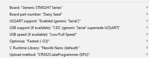
If you have these settings (specifically the ones related to USB support, and U(S)ART support:
then generic Serial.println should be functioning.
If you’re able to program the Daisy properly from Arduino then it seems you have everything installed correctly, and USB is functioning. Are you able to see the Daisy show up in your Device Manager? From arduino it would show up as a "STM32 Virtual ComPort)
With the above settings, this sketch works without issue:
int val;
void setup() {
  // put your setup code here, to run once:
  Serial.begin(9600);
  val = 0;
}

void loop() {
  // put your main code here, to run repeatedly:
  delay(100);
  val++;
  Serial.println(val);
}