Hey everyone! I’m working on a flexible guitar pedal effect platform based on the Daisy Seed. This all started because I wanted something like the Daisy Petal, but in a smaller more pedal board friendly format. I came across the PedalPCB Terrarium in my search for something similar, but was disappointed that it was only mono, so I decided to build my own.
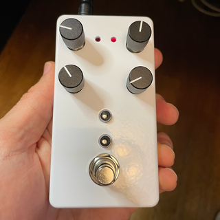
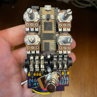
The first design I made was for a really small 1590B sized enclosure. In the spirit of the Terrarium, I kept the design as simple as possible only using through-hole parts, so that it’s pretty easy to assemble. The main advantages of this one over the Terrarium is that it’s more compact, has stereo in/out, and has midi in/out.
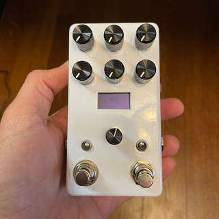
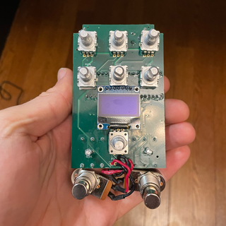
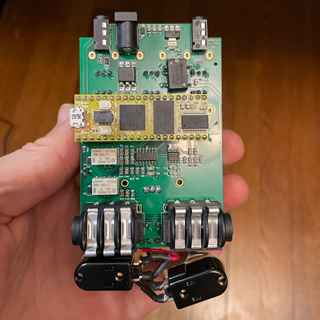
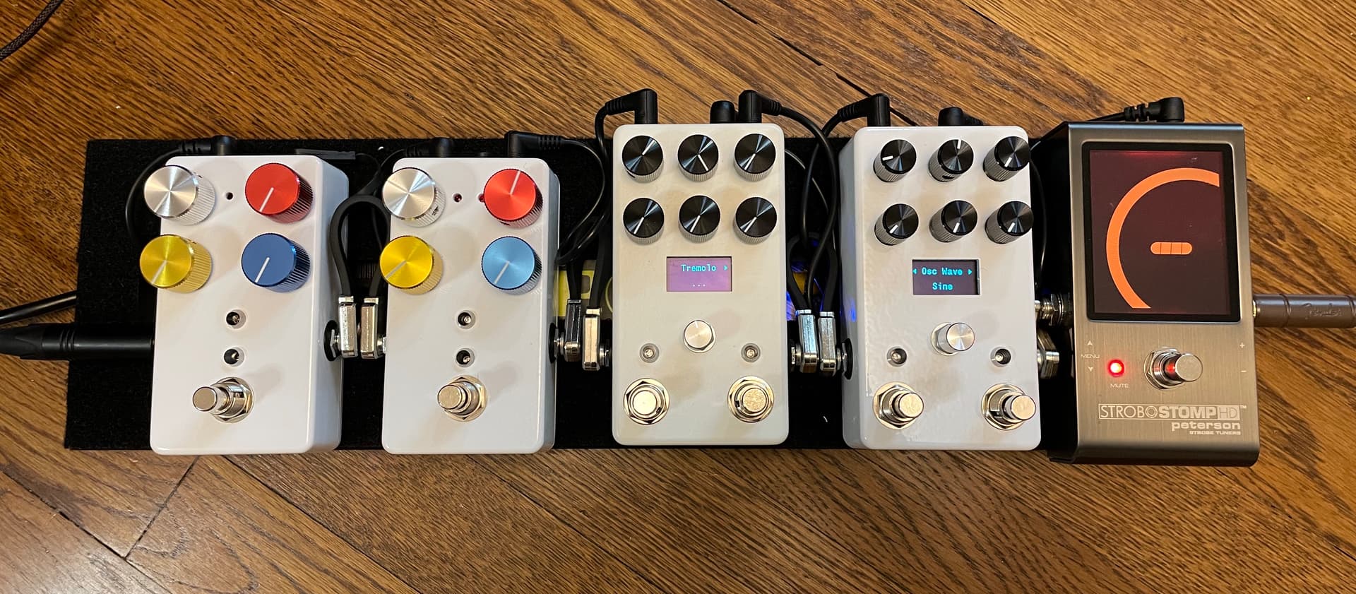
The second design I made is a bit closer in features to the Terrarium. It’s a 125B sized enclosure with 6 knobs and 2 foot switches, but I was also able to fit in a small OLED screen and a rotary encoder to allow for creating menus and other configuration options. This one is also Stereo In/Out, Midi In/Out, and I also used relay based switching for “true bypass” when the effect is not in use.
Making these hardware designs has been a lot of fun and I’ve been through a couple of iterations already on the designs.
If anyone is interested in building one from my designs, it should be pretty easy, and I’m happy to advise (I’m on the discord a lot). I’m also looking for contributors to the project if anyone is interested in helping with hardware designs or writing software for the devices.
It’s probably possible to do the SMD work at home, but I simply had JLCPCB both manufacture the PCB and assemble it with the SMD parts. I was sorta amazed how “cheap” it was to do this. Get 5 almost fully assembled PCBs (there are some parts you have to still solder yourself that aren’t SMD) for ~$150 shipped to my door. Down side is you have to order 5 not 1.
I also made a through-hole part only version but it’s the smaller size enclosure with 4 knobs and no screen. That one is more more friendly to build at home. Doing a through-hole part version for the one with the screen might be possible, but once I got comfortable having JLCPCB assemble my stuff, I stopped trying to deal with the layout and space constraints of using all through-hole parts.
Happy to help you walk though the process of getting one made by JLCPCB if you are interested. It’s pretty straight forward. Main downside is you end up with 5, not just 1
Very interested in building one (or five) of these units! I’m not really sure where to get started. I have experience writing DSP code and using CAD software, but know nothing about PCB fabrication (I’ve gotten as far as downloading KiCad).
Then you upload the resulting files to the website and they will give you a quote. I’ve been meaning to write up a tutorial on how to do this, but I haven’t had the time.
How comfortable are you with a soldering iron? If you are comfortable and have a lot of basic parts lying around (resistors, caps, etc). Only getting the PCBs made and then assembling the 1590b board with Through-Hole components is pretty easy.
If you don’t have a bunch of components or aren’t used to soldering, it may be easier to simply have JLC assemble the board too. The 125b design is made with SMD parts with having JLC assemble it too. You’d also have to generate these files from the KiCad project:
the BOM in the proper format is included on the GitHub repository, but the other files are not.
There are still a few parts you’d need to hand solder after receiving the boards, but it’s was less to solder than the 1590b design.
Happy to answer questions, but hope that gets you pointed in the right direction.
Also, I do have some extra PCBs from the last batch I ordered, if you are in the states, I’d probably be willing to send you one.
To make everyone’s life easier, I uploaded the exported Gerber Files for getting the 1590b PCB easily made by JLCPCB and included instructions on how to order them. This requires no knowledge of how to use KiCad to get the PCBs ordered.
I’ll do the same for the 125b version soon too, but it’s more complicated since it involves using JLC’s assembly service to have the PCB made and assembled with the SMD parts.
Wow, thanks for such a quick response (I’m just getting to this now)! Yep, definitely interested in an effects chain with a few units. I’m inclined to build the 125b version for the extra footswitch and the display…
Between the documentation you linked, your instructions here, and the readme on GitHub, I think I understand the process now. I generated the Gerber files from the .kicad_pro file in GuitarPedal125b/pcb and just need to make the order with the BOM spreadsheet.
Alright, I exported all the files and went through the sequence of ordering pages in JLCPCB. It looks like U2 (link), U7 and U8 (link) are out of stock but I think I can order them from Mouser and hand-solder them.
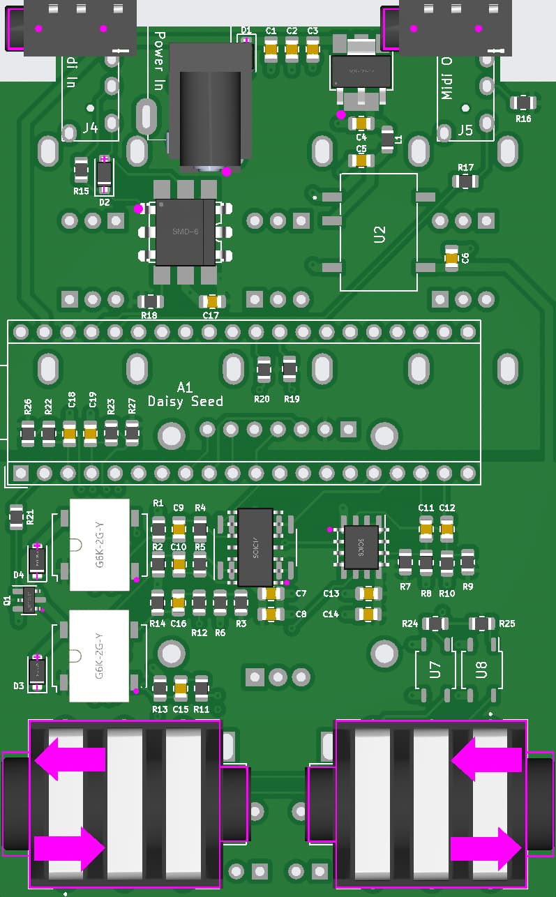
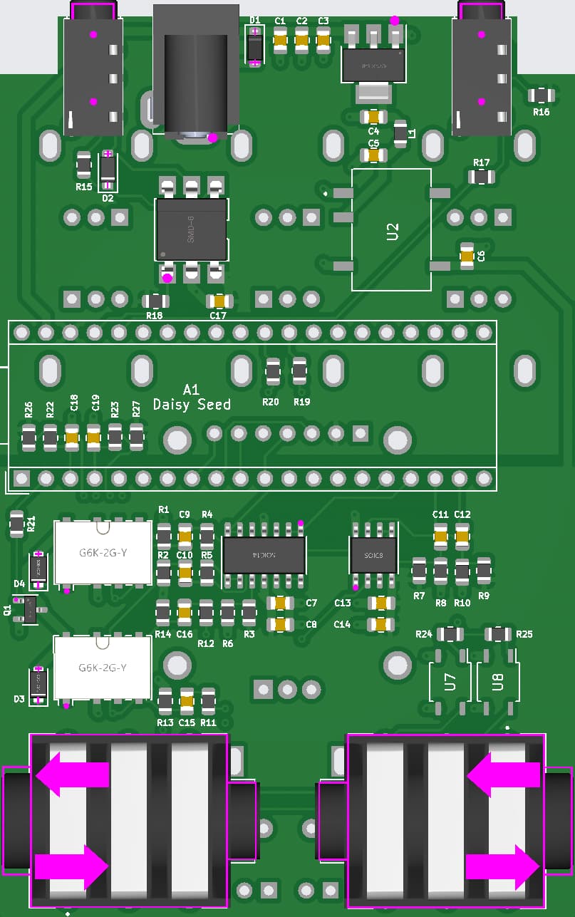
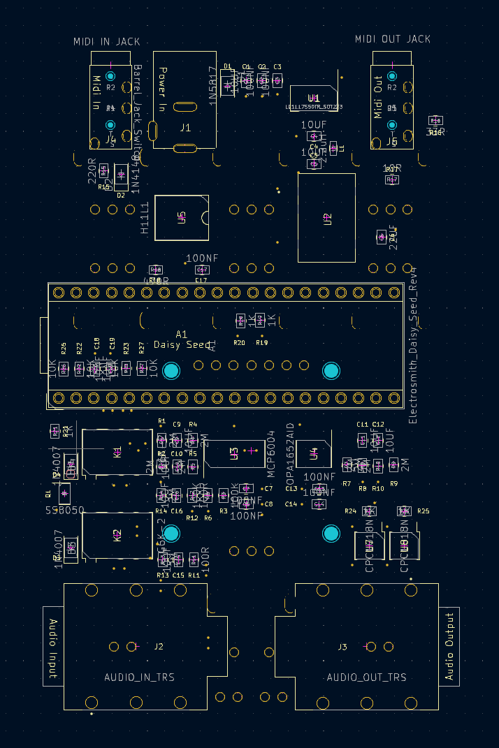
When I uploaded the BOM and centroid files most of the SMD components were incorrectly oriented; the JLCPCB tool has an “align” feature which, I think, got most of the placements right (based on cross-referencing the 3d model in KiCad). I had to fiddle a little with the power jack to get its pins to line up with the through-holes. I’m also not confident U5 is oriented correctly; I don’t know how to read the orientation info on the silkscreen.
This is the layout immediately after uploading the BOM / centroid files:
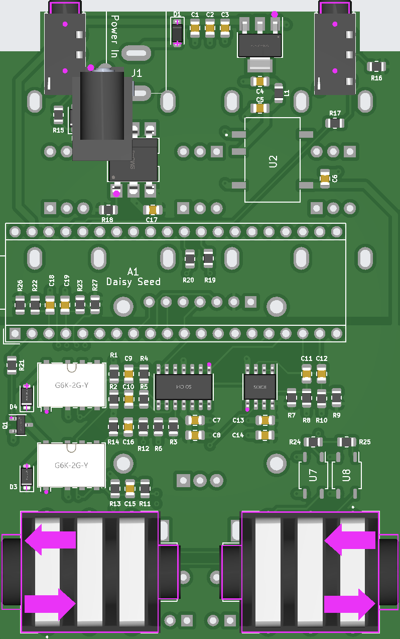
Wow, thanks a lot! Yep, I didn’t know how to read the orientations of the components from the KiCad file. Indeed those three were upside down; all the diodes and other asymmetric components turned out to be the right way around.
Yes, I should make note of this in the build docs. KiCad’s footprints are oriented differently than the footprints that JLCPCB uses in some cases. You can manually rotate them in that 3d viewer tool you are looking at. Their techs would likely also bring this to your attention in their review, but I find it best to do the rotations. I haven’t had any trouble doing that.
Also, for the components they don’t have in stock, you can pre order them from them usually (their global parts ordering) before you do the order and then they will assemble those parts too, but it’s not too bad to hand solder them.
Also, beware that POT5 gets in the way slightly with the oled screen when assembling. I ended up having to trim off the mounting tabs from the pot and shifting it up about 1mm to get it out of the way. It still assembles, but it’s a tight fit, and it’s not ideal. I’m working on an updated PCB that pushes the oled down about 1mm to remedy this, but I haven’t pushed it to GitHub yet.
I’ll keep an eye on the Github repo, then! I still haven’t placed the order of the PCB’s – had to preorder DC-DC converters (PDS1-S5-S5-M-TR) and optocouplers (CPC1018N) which seem to be the only nonstandard parts on the design.
By the way, I forgot to mention that the reason I’m trying to build your pedal is that I’ve written some C++ effects and synthesizers that currently run just on my laptop; I’d like to make it easier to perform live with them, rather than having to lug around an interface & computer to gigs. So I’m definitely interested in developing software for this device!
I updated the PCBs on Github with the mentioned fixes. That’s awesome about your project! I definitely could use some contributors on my project on the software side if you want to make improvements. It would be nice to take my template software example and make it more flexible so that different effects could be easily swapped in an out in a more modular way.
Thanks! I generated the new Gerber and drill files from your design – also ordered the two components missing from JLCPCB’s parts library via their sourcing services. So I should be ready to pull the trigger on the order soon and get to messing around.
I also updated the Tayda drill template to reflect the updated screen position. Tayda Electronics Drill
Firstly I wanted to say THANK YOU @kshep for this project. I was inspired to look into Daisy Seed after seeing Takumi’s “Let’s create an Effects Pedal” with a Daisy Pod video on YouTube.
Sadly my local vendor is out of stock and I kind of wanted something a little more pedal like, small footprint, with more knobs and screen.
Stumbled across the Terrarium project, but saddened to see it only run Mono, and no display.
Per chance I stumbled across your project and all kinds of alarm bells started ringing! Yay!
I’m based in Sydney, Australia and have a small committed little DIY group that jumps on little projects like this, we have built Eurorack modules, Monome open-source bits and one of the guys has a Seed kicking around and so we’re going to build these, have 3 of the kits accounted for and will no doubt find holes for the other 2. (I say kits because I’ll source all the additional parts, we each take part. I’ll do the enclosures, someone else will grab the seeds, another the pots/encoders etc).
I’ve ordered several projects from Gerbers with JLCPCB, but never used the SMT service, keen to give it a try and would love to use your prepared Gerbers @alo.bu if you wouldn’t mind sharing?
I’m way better at building than coding, but have an Organelle and Norns with basic .Pd and Lua knowledge, enough to hack it at least and look forward to using this as a development platform.
Again, thank you all for your kindness and generosity in advance.
@mattallison: Linked below are the Gerbers (zipped) and centroid file (.csv) for the PCB manufacturing and SMT service. You’ll likely need to source the two nonstandard parts yourself – this could either mean ordering them delivered and hand-soldering, or using JLCPCB’s parts ordering service.
Once you’ve uploaded the Gerbers, centroid file, and BOM, you’ll need to reorient some of the components manually using JLCPCB’s online tool to match the KiCad schematic. Good luck with the build!