@mattallison@alo.bu Glad you all are finding my project useful. I spent some time this morning writing up detailed instructions on how to order assembled PCBs from JLCPCB. You can find the instructions and pre-exported Gerber files here:
I hope that makes it even easier for others to make their own pedal like mine. Please let me know if anyone finds any issues with the instructions or parts that are unclear.
This is awesome! Glad you were able to build one from the files on GitHub! I think you are the first person other than me to have one built. Glad to hear it’s working as expected. Let me know if there is anything to improve on the documentation to make it easier for anyone else wanting to build one.
The documentation was crystal clear! And flashing the example program to the Daisy worked on the first try. I’m going to have a go porting some of my C++ audio code later this week.
I’m not sure what is next on your to-do list for this project, but I’d love to be involved in the next iterations of the design!
It’s been a while since I posted and update with my progress. I’ve made a lot of improvements to the software and built a mini-pedal board using 3 of the custom pedals. I’ve attached a video explaining some of the new capabilities. Highlights include:
Support for Multiple Effect Modules on each device.
Custom mapping of effect parameters to physical knobs (so you don’t have to dig thought menus)
Full control over all parameters via a flexible on screen menu
Full Midi Control over any effect parameter and the ability to easily re-arrange the order of effects on the pedal board.
I’ve only built a few simple effects so far. A modulated Tremolo, a simple Chorus, a simple Overdrive, and a simple stereo effect that Auto-Pans a mono signal between the left and right channel. I’m having a lot of fun playing around with it now that I’ve got the basics working with the software and I’m hoping to continue making more effects. If any one is interested in making effect modules for the pedal, let me know.
I am really enjoying this project! I am in the process of building this pedal following your great instructions. I saw in the YouTube video it looks like you have some cool new knobs for the 125B. Are those in 6mm and would you be willing to share the source?
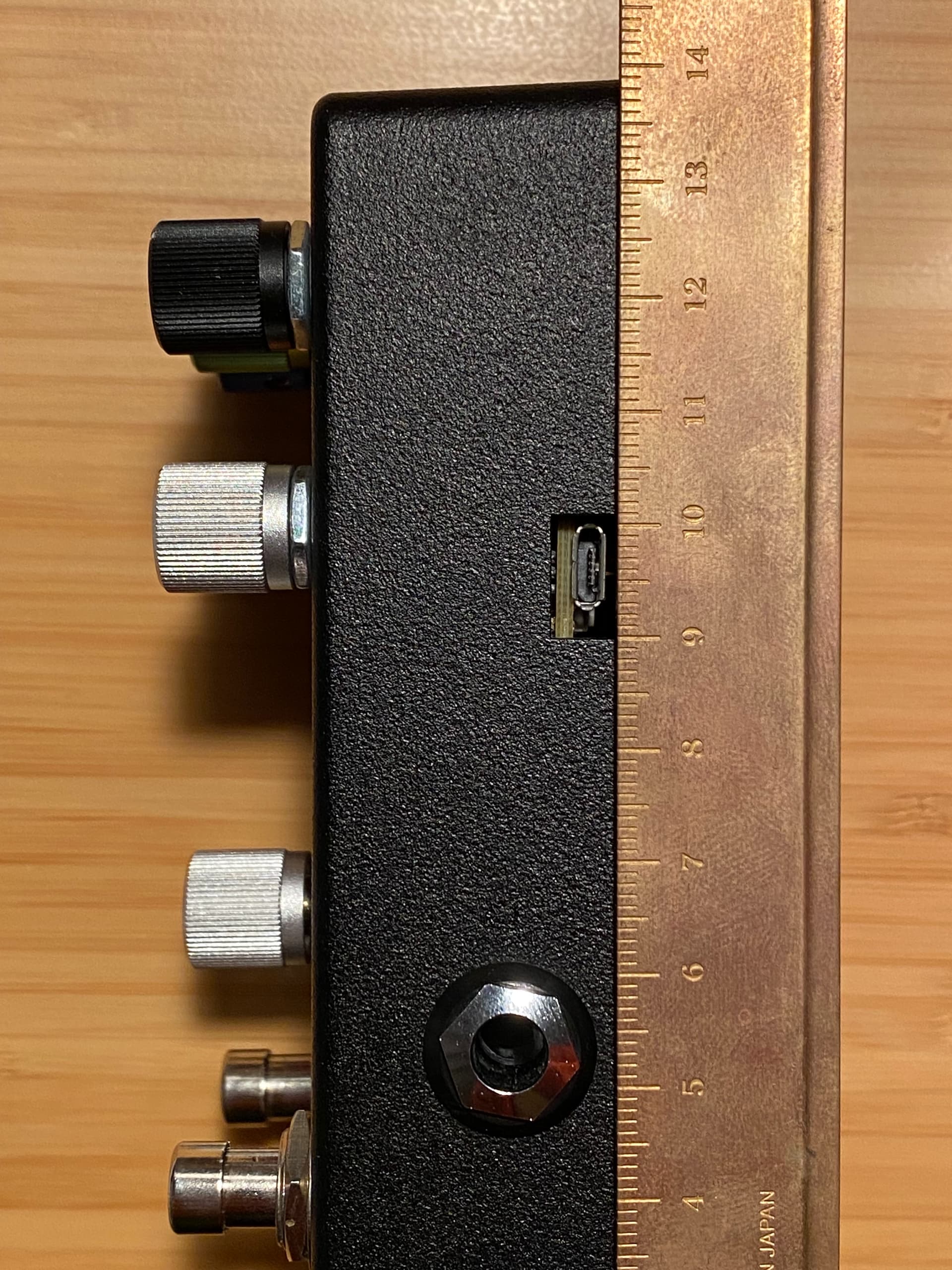
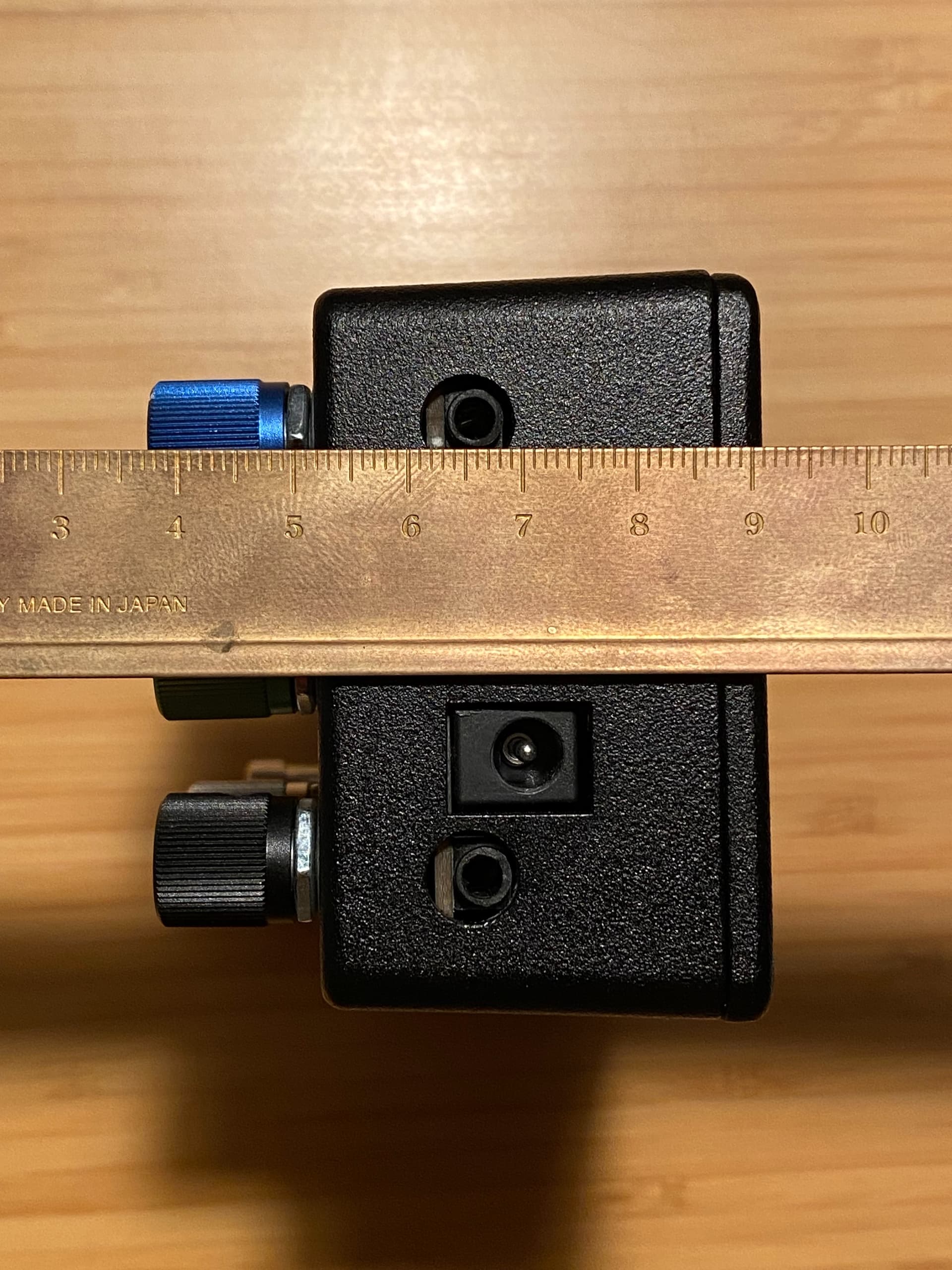
By the way, if you plan to use the Tayda drill service, I’d suggest moving the hole for the micro-USB port up (away from the audio jack) by about 1 mm.
I’d also suggest moving the holes for the TRS midi jacks down (toward the backplate) by about 1 mm. The enclosure fits very snugly; this would make getting the PCB in and out a bit easier, in case you run into some electrical issue once the thing is fully assembled. I’ve only managed to take apart one of my units fully, and I had to shave down the plastic midi jacks to get them to clear the enclosure.
Good suggestions. Might be worth making the midi jack holes wider too. Part of the problem is that the midi jacks need to stick into the wall of the case, if they don’t stick in far enough the 1/8 trs cable won’t actually seat properly. I had a build where I tried to pull the midi jacks down on the pub, but then the plugs wouldn’t make full contact.
Side note, I’m considering ordering another batch of PCBs for the 125b pedal. If anyone wants one, I’d probably be open to ordering a few more and mailing them to folks. Message me directly if interested.
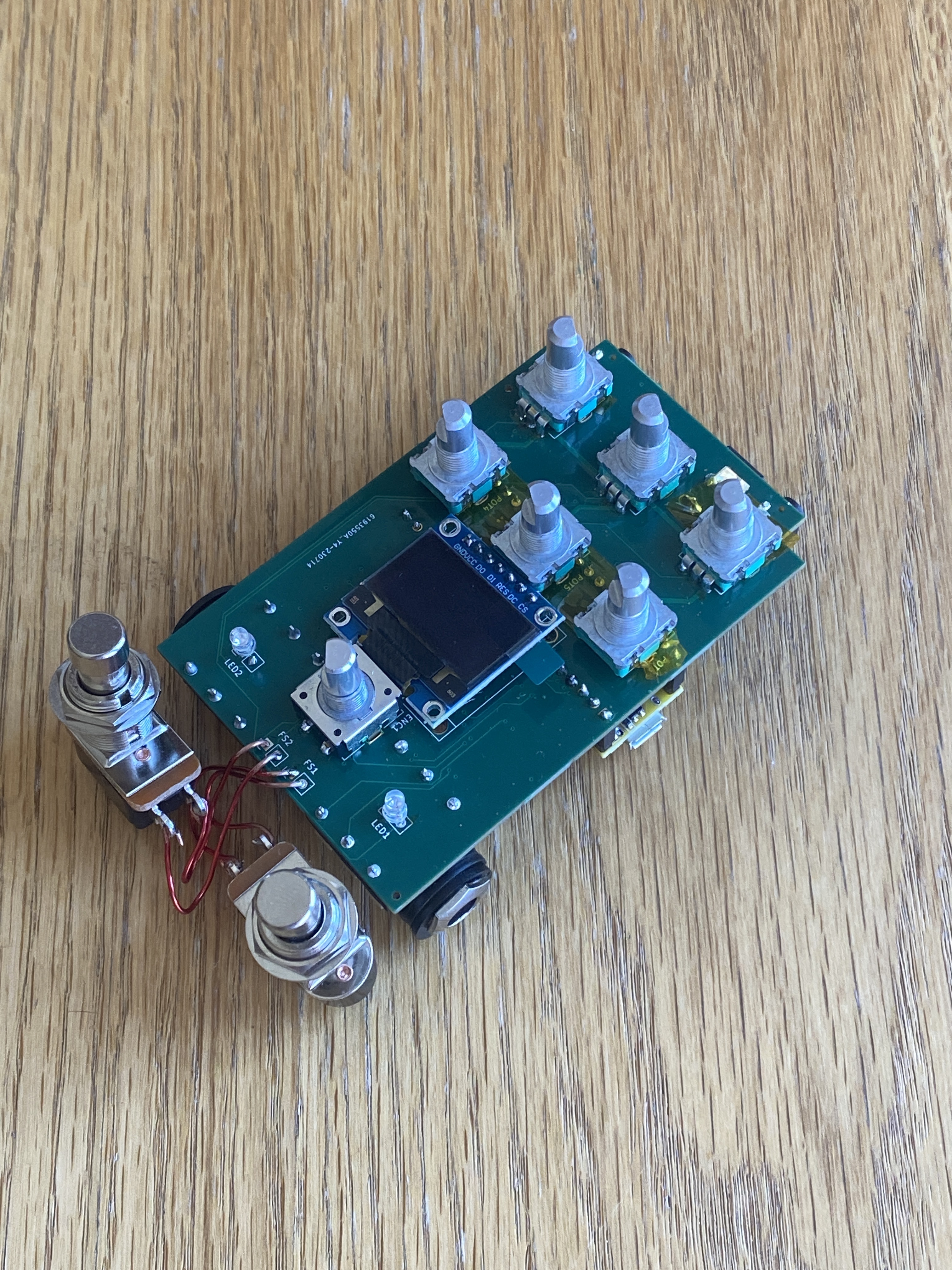
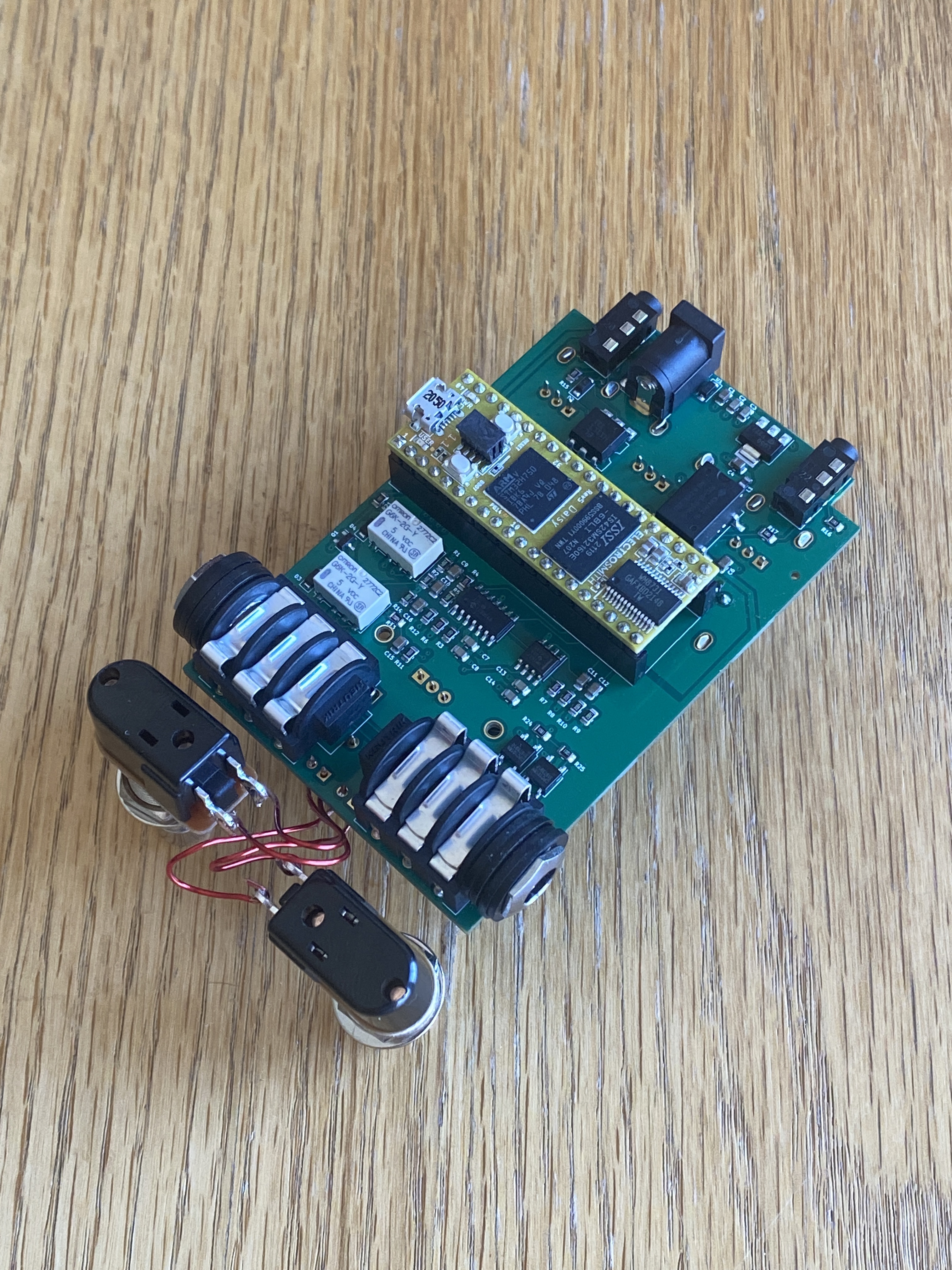
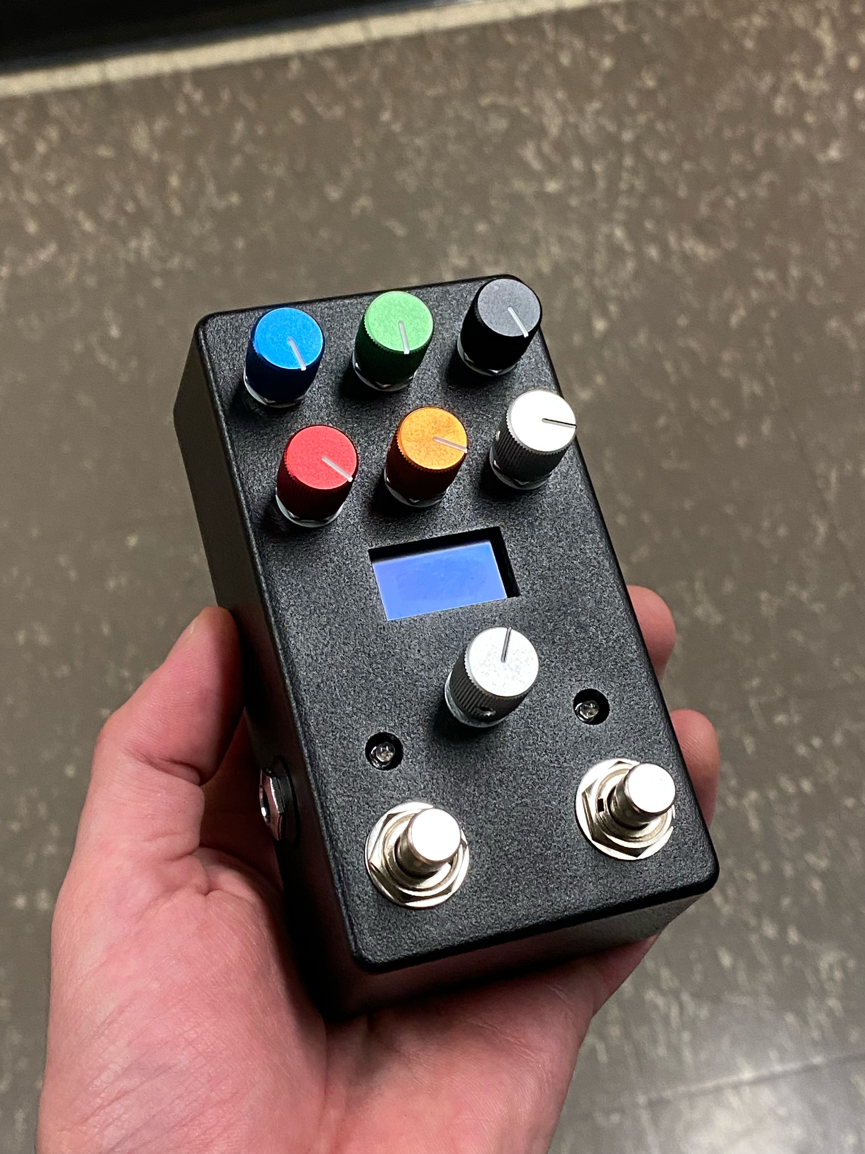
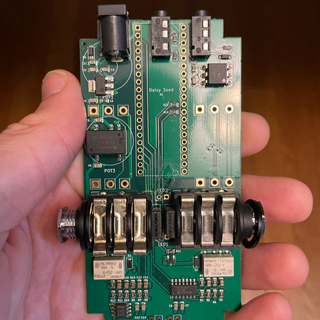
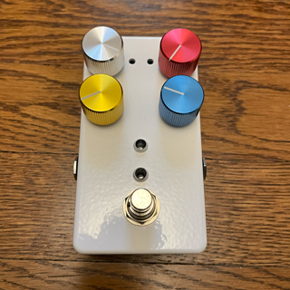
Quick update on my guitar pedal project. I added an SMD version of the 1590b sized pedal to my GitHub repository. It has the same features as the through-hole version of the 1590b pedal with relay based true bypass in addition. Much easier to get this size pedal built now since a fab like JLCPCB can do most all of it. Here’s a pic of the circuitboard and finished product!
I’d be really interested in getting my hands on a PCB of the 125b version and building one of these. I’ve just built a terrarium and would be really keen to have a go at this as an upgrade! I’m based in the UK though so not sure if it would be more trouble that it’s worth for you to order the PCB and ship over here.
(I’m also new here so can’t yet send you a DM - hence the message here )
looks like ill have 5 of these to play with or sell eventually.
is this the main thread with the most activity surrounding development of your daisy seed guitar pedals. confused you a little with guitar ML for a bit cause hes cloned your project…are you going to port/clone the neural seed?. and what hes calling seed when released.?
it looks like you’ve shared the main code for a guitar pedal system, including handling audio processing, effects, user interface, hardware interaction, and MIDI. The code is well-organized and includes various modules for different effects.
Here are some key aspects of the code:
Hardware Interface:
    The code uses the GuitarPedal125B class for hardware interfacing.
    It initializes the hardware and sets the audio block size.

Effect Modules:
    Several effect modules are defined, such as Modulated Tremolo, Overdrive, AutoPan, Chorus, Chopper, and Reverb. Each module inherits from BaseEffectModule.
    The available effects are initialized in the main function.

User Interface:
    The GuitarPedalUI class is used for handling the user interface, including displays and controls.

Audio Processing:
    The AudioCallback function processes audio samples.
    Knob values, switch states, MIDI messages, and other controls are handled to control various aspects of the audio processing.

Settings and Persistence:
    The code utilizes persistent storage (PersistentStorage) for storing settings across power cycles.
    There are mechanisms to save and load effect-specific settings.

MIDI Handling:
    MIDI events are processed in the HandleMidiMessage function.
    MIDI Through functionality is supported.

Crossfade and Bypass:
    Crossfade functionality is implemented for smooth transitions between effects.
    Bypass logic is implemented, considering relay bypass, mute, and toggle timing.

Debug Display:
    There's a debug display option for showing debug information.

UI Updates:
    The UI is updated regularly, handling user input, active effect changes, and other UI-related tasks.

Threading:
    The main loop handles various tasks, including UI updates, MIDI handling, and saving settings.

Initialization:
    The code initializes various variables, including knob and switch monitoring systems.

Time Handling:
    Time-related operations are performed, such as handling elapsed time and setting tempo.
It seems like a comprehensive guitar pedal system with support for multiple effects, a user interface, MIDI integration, and persistence.
Exciting that you are getting some made! These days I’m mostly focused on the software side as the hardware is in a pretty stable place. The above is a pretty good summary of what the software framework can do so far. Trying to make it easy for anyone to add custom effects. The framework can handle all the standard stuff like switching effects, managing parameters, storing presets, mapping knobs to parameters, etc, etc. It’s also pretty easy to extend the framework to work on other types of hardware. It currently runs on all my hardware as well as the Terrarium.
There are a few folks actively contributing to the project at the moment. It’s definitely getting better by the day, and I look forward to see what you create for the hardware!
Amazon.com any of the colors is fine, but definitely make sure it’s SPI or it won’t work on the pcb.
As for the mouser parts, the encoder and pots look correct. The headers however look like 20pin male headers. You want female headers for the PCB since it creates a socket for the seed which has male headers on it.