Hello all i have started programing recently, and soldering basic stuff.
My question is how many for example buttons i can have in a daisy seed or a combination of pots.
I believe the GPIO is used for pots and buttons.
Thanks from now.
I cant describe how happy/excited im !
Welcome!!! Glad to hear that you’re excited to get started ![]()
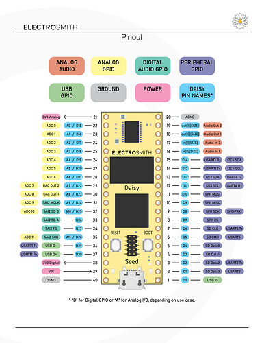
I recommend checking out the Seed’s pinout diagram.
All those GPIO pins with the letter D can be used for digital I/Os (like buttons). For potentiometers, you can only use the GPIO pins with the letter A. Of course, you can expand the number of ADCs by using a multiplexer, which you can learn about here.
Thanks for the answer !
i forgot about the multiplexer thing.
I’m actually looking into the same thing right now. Takumi has a documented demo of an 8:1 multiplexer. I haven’t seen anyone design a small PCB with a 32:1 multiplexer but I’m considering that since something like that would seem idea for prototyping and microcontrollers in general. Considering the something like the following:
https://www.digikey.com/en/htmldatasheets/production/863541/0/0/1/adg726bcpz-reel
Figuring $20 and a bit of software and you could have enough IO for something with more LED’s, buttons, or pots which seems common on most audio instrumentation (if you look at timing based stuff it is normally 8, 16, or 32 and then an array of pots) so it seems like some PCB like that could be an option. I’m considering doing something with at least 18 RGB led’s and 18+ buttons plus a few pots and at least one encoder so when you add up the pins used it’s beyond the base of the Daisy but having a Daisy+ expansion board could be something to consider. Basically big guitar pedal with lots of visual I/O stuff in that case.
If you look at other companies they model stuff kinda like generic port I/O so they have standardized connectors and products to match oftentimes. Might be something to consider with Daisy which it seems many people already do but they use a socket for the entire board pinout (except the pins for the debugger).
To answer the initial question it depends on what type of potentiometer you use but most of them have a 3 point connection where ground, output signal, and voltage reference all are used so it basically uses power rail connections then one ADC pin. The Daisy appears to have 11 total of those without a multiplexer and since digital pins can’t really make sense of anything other than a 1 or 0 signal they can’t be used, only the ADC signals. So with just the Daisy it seems like you can easily get 11 potentiometers going pretty easily. You can use digital pins (Daisy Pin Names*) for buttons since they operate on a 1/0 system unless I’m mistaken so that gives some pots and buttons to start off with. Using the onboard LED as an indicator until you have some other LED’s is also a good way to quickly test stuff. There is normally a blink example for controllers that shows how to do that and it is very helpful for debugging and visual process flow control.
This shows kinda what the potentiometer is doing. There is a wiper that spins around and increases or decreases resistance based on it’s position which is determined by the knob you turn.

