I just recently got a daisy pod and after a few days of playing around with it and exploring the examples I realised that my model is slightly different from any other I’ve seen on the internet, including the electro smith website and the documentation in the daisy examples.
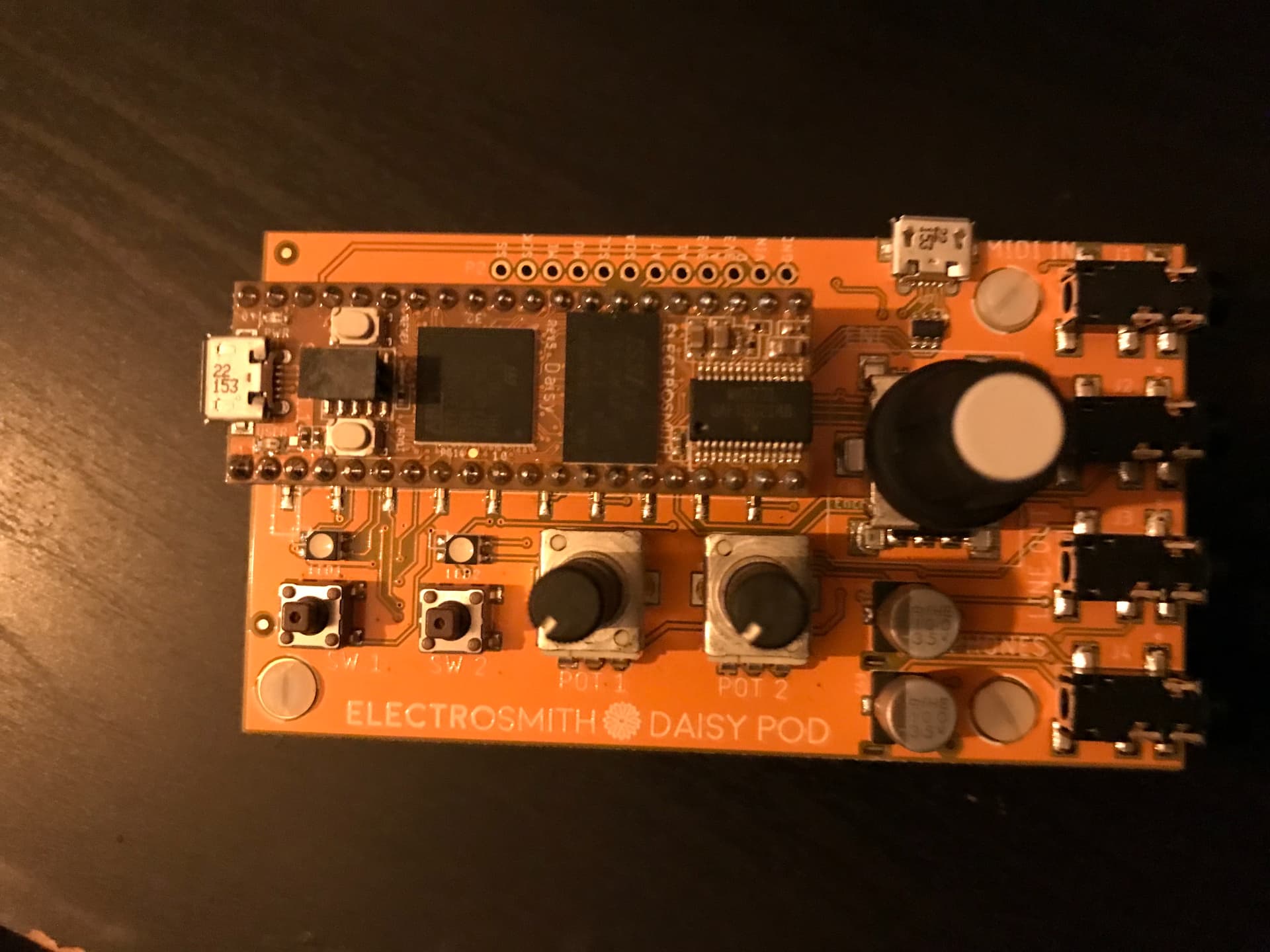
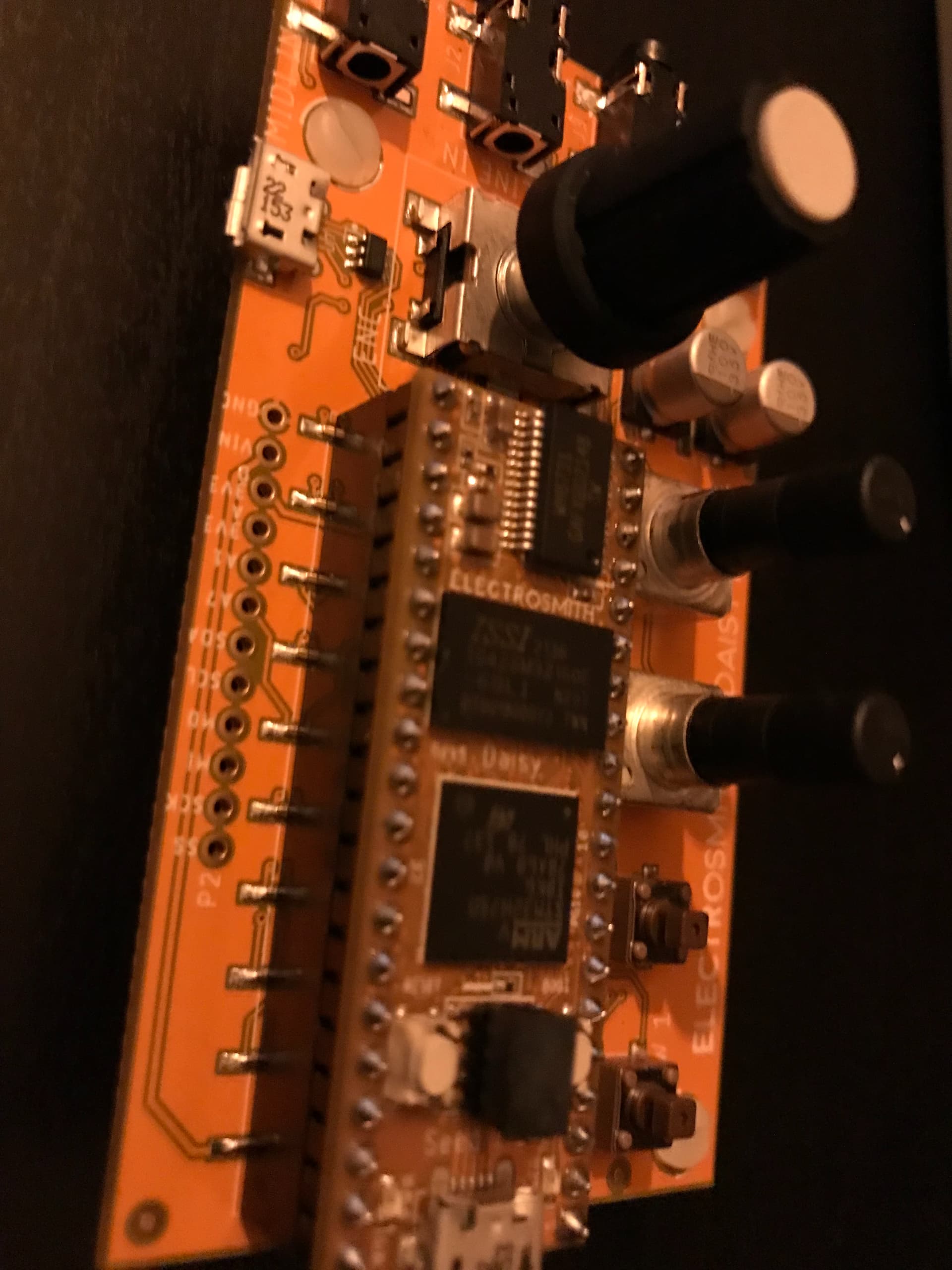
It’s nothing major as the pod works just fine, but I realised this difference when I wanted to integrate a an OLED display. Essentially the connectors that join the Seed to the Pod are of the smd kind. Moreover the pin connectors only have one slot that connect the Seed to the Pod, and there is no second row of connectors running on the side of the seed pins, which would allow me to access each individual pin of the seed.
Although there are some extra connections on the Pod’s pcb for interfacing with the seed it’s only 12 of them, nowhere near the full potential of interface expansion.
Does anyone else have the same board as me? Is this a new revision of the board or something? it’s weird tho as not even the documentation mention anything.
That must be a revision? Mine has the double sockets, but I’ve had mine for a long time… I actually ordered mine just to take the Seed out during The Great Seed Shortage of whenever…
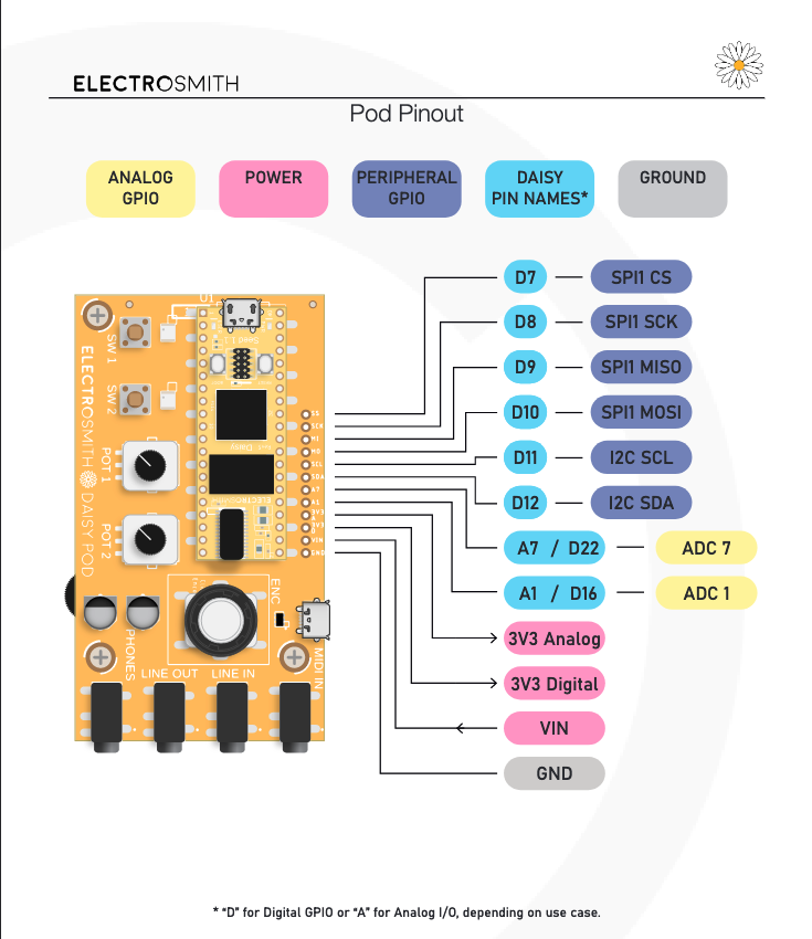
I have the original kickstarter Pod and have gotten to know the schematics fairly well, they’ve basically just broken out the pins that are not already consumed by the Pod architecture. Whether you’re using an OLED with SPI or I2C interface you do still have all the SPI and I2C pins, the Reset line is the one that could be an issue depending on what you want to do. I recently ported the oscilloscope program from this topic Is an Audio In OLED oscilloscope possible? to the Pod so it would use the built-in pots, and used D16 for the Reset since I wasn’t connecting anything else (my display is SPI).