This is something that has stumped me for a while now.
What is the best way to go about handling “Clock Input Tempo Detection”? The goal isn’t to just advance a sequence every time a GPIO pin goes HIGH. That is easy. What I find difficult is accurately syncing an internal clock to an external one.
For example, take some analog clock signal from a separate piece of hardware (ei. +5v trig/gate) as an input into an MCU GPIO, and sync an internal clock signal to it.
There are loads and loads of open source euro modules out there that do this, but I have yet to find an explanation of the concepts for coding one yourself.
I have been looking at some open-source modules like the 4MS SCM, and I am starting to think that just using a Timer that counts the number of ticks between two rising edges of an external clock pulse, and then just dividing that down to get a multiplication of the external clock is the best way to go… Perhaps a phased locked loop is best when you need to match the frequency of a high frequency signal?
I agree with @scottc11. Using a timer is a simple solution that should work fine.
In general, if you have a slow input to measure, you count the time between edges with the system clock. If you have a really fast input, you count edges over a fixed time interval. The hardware timers in the Daisy processor are more than capable of both operating modes, running at the system clock rate.
Then it is just a math exercise to average or interpolate the period/frequency, divide it, multiply it, phase shift it, or whatever, to compute your internal event or sequencer clock period. You can use the next incoming edge to reset or resynchronize your internal clock to the input.
I had a lot of experience with PLL’s in my previous life. I honestly can’t think of a scenario where a PLL would be a more appropriate solution, unless I don’t understand the context. Perhaps if you were trying to recover a tempo from an actual note stream, rather than a tempo signal …
If the goal is to synchronize to an external ‘beat’ or tempo I could see a PLL as a good solution, although it might be implemented in software instead of circuitry.
I’m confused as to what you are trying to do. In your initial question, you referred to an “analog clock signal” - in what sense is it analog? Are you going to read it via an AD port or just a regular old GPIO pin?
Even though I’m confused, I thought this link: https://www.clear.rice.edu/elec301/Projects01/beat_sync/background.html
might be helpful, if only by clarifying the issues-problem. See the left hand menu item:
Beat Detection Algorithm
for more details. It’s all in Matlab. They mention 'We adapted a beat detection algorithm from the MIT Media Lab to Matlab for our project. " - I don’t know what it originally was written in.
By analog I just mean some arbitrary clock signal coming from another piece of hardware which gets read by a GPIO.
I am aiming to synchronize my sequencer (controlled by an MCU) to an external clock. My sequencer has a “resolution” of 96 PPQN - so each external clock signal the MCU receives needs to be broken down into 96 sub-steps / ticks.
I want to say the beat detection stuff is perhaps overkill for this problem? Because that algorithm / approach is all about detecting peaks in a signal and then pulling out time information between each peak etc. but idk - the same math applies for sure
After doing some reading into STM32 Timers (Mastering STM32, great book) I am pretty sure that setting up a Timer in Input Capture mode will probably do the trick.
I guess you could accomplish “Input Capture” in a less fancy way by just reading the timer every time the GPIO Interrupt fires, but I wonder if there are any latency issues with this approach .
I agree, the beat detection stuff is overkill, because you are starting with a clock signal. To my mind it’s a digital clock signal, but I’m not going to argue about that - it’s a deep-subtle difference. I think the timer approach that scottc11 suggested above could work, the PLL approach (either software or hardware) would be the ‘general solution’.
@scottc11 Did you happen to figure this out? I’m currently trying to implement a similar thing and I’d definitely appreciate any advice or source code that you have.
So I did end up figuring this out, but I don’t know how compatible the code will be with the daisy platform. What I mean by that is you may need to breakout CubeMX to generate the code, because they use a different chip than I do.
The way I went about it is by using a Timer in “Input Capture” mode. I believe this method is the most accurate way to detect the time elapsed between incoming pulses. It doesn’t use any CPU cycles to calculate the number of “ticks” between two rising edges on the gpio pin. This value is simply stored in a timer register and accessible when you need it via __HAL_TIM_GetCompare().
Now if you clock your timer directly from the system core clock, then that timer is going to increment its counter extremely fast, so fast that you will find the timer overflows before the next rising edge of the input occurs. Since we are generally trying to determine the time between quarter notes or 8th notes, the timer needs to be configured to sample the frequency of really slow signals. To do this I used an additional timer to “drive” the timer configured in input capture mode.
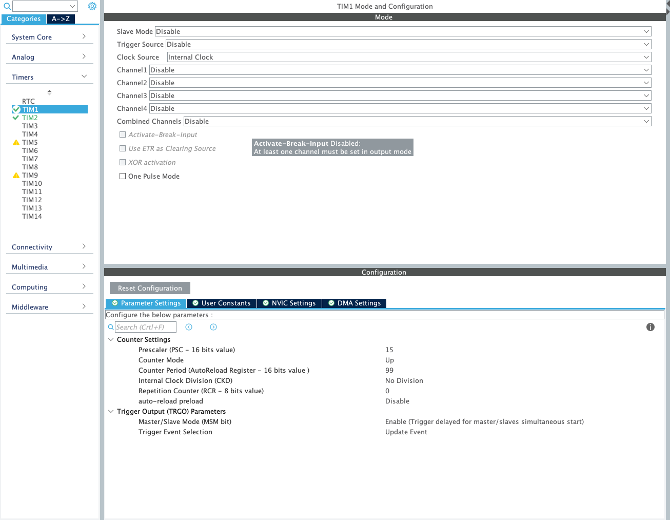
This was probably a poor explanation… but here are the CubeMX Config screenshots of my TIM1 and TIM2 configuration:
To clarify, TIM1 is being use as the Master clock source for TIM2.
TIM2 is configured in “Input Capture Mode” which triggers an interrupt routine every time there is a rising edge on “Input Capture Channel 4” (which is just a GPIO).
The interrupt function looks like this:
void HAL_TIM_IC_CaptureCallback(TIM_HandleTypeDef *htim)
{
  if (htim->Instance == TIM2)
  {
    __HAL_TIM_SetCounter(&htim2, 0); // reset TIM2 counter after each input capture
    inputCapture = __HAL_TIM_GetCompare(&htim2, TIM_CHANNEL_4);
  }
}
This is really just the beginning of the battle though. After you get to this point you would then start adding code to that interupt routine which clocks your sequencer or do whatever your application needs to do with that inputCapture value.
Nice work, thank you for sharing! Did you decide not to use Daisy for the sequencer you’re designing, or are you using Daisy augmented with additional hardware?
I took a stab at it as well. I was able to create a metronome that (roughly) detects incoming BPM from GATE In pulses by using a libDaisy::TimerHandle and computing the delta between each clock pulse.
Things worked fine until I asked it to do something in between pulses (e.g. play something every 16th note). It seems like the additional computation time throws the delta way off. Since, to my understanding, Daisy isn’t capable of multithreading, I don’t know how this could be avoided on a stock Daisy Seed.
Here’s the (currently disabled) source code if anyone’s curious. Excuse the hacks and general ugliness, I’m new to embedded and C++. Essentially, pulse() is called upon every trigger to GATE IN 1, and update() is called over and over in the main event loop.
By the way, I watched the demo video of the sequencer you’re making. Really cool!
Daisy is capable of multithreading if you run an RTOS on it, what it’s not capable is running more than one thread in parallel as there’s no SMP. But you don’t really need either here.
You could try calling update() in your audio callback instead, that would guarantee that your timer is updated for every block of audio. Placing it in main loop makes it run at lower priority and you’re competing with other hardware which can be slow if peripherals are used in polling mode.
I’ll give that a shot! How come placing it in the main loop makes it run at lower priority? Is there something in the Daisy code or hardware that governs priorities of certain operations?
So this is why I think Input Capture Mode is best, because you don’t have to compute anything. Once you get the input capture value, you can mangle it however you want without worrying about latency etc.
I’ll try and post some code when I get around to it. I am suppose to polish my clock up this week!
I honestly started it way before the daisy came out so I was already invested in the stm32f4 series and I just kinda wanted to learn all the low level stuff.
I’m resurrecting this old thread because I am trying to do exactly what the OP mentioned was “easy”
My goal is to just advance a sequence every time a GPIO pin sees a rising edge (goes high)
I have code that works on an STM32G4, but it isn’t running a real time audio, and instead simply writes a voltage to the DAC on each clock input.
I simply use a rising edge interrupt on a pin which calls
//  Code that works on a  simple non DSP STM32G4 program
void gate() {
  clockInput = true;
}


if (clockInput) {
 count2++;

      if (count2 > countSize)  {
        count2 = 0;
      }
}
edit: oops I got it working.
Working version of the code above now found below
patch.gateIns[1].Trig() works for my use case it seems.
At least I’ve got it working with a modified loop example.
I’ve only had a Daisy Patch for a few days and I am constantly impressed, nice work electro-smith. I’m a musician who pretends to code really so it says a lot that this framework was instantly accessible to me.


 .
.