I have seen community members getting a multiplexer to work Patch SM (here and also here with some modifications to libDaisy and etc), but we should offer a simple example code in the DaisyExamples when we get a chance in the future.
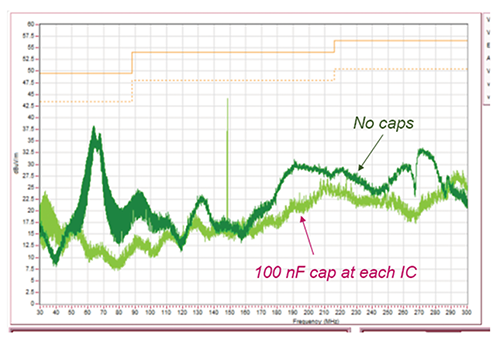
All CMOS chips must have a decoupling capacitor across the power pins.
This is even more needed when using a breadboard, and especially using high speed digital MCU along with CMOS on a breadboard.
If anyone couldn’t get this to work, try it again with a 100nF capacitor going from pin VDD to VSS.
From the datasheet
Each VCC terminal should have a good bypass capacitor to prevent power disturbance. For devices with a single supply, a 0.1-μF bypass capacitor is recommended.
It is acceptable to parallel multiple bypass capacitors to reject different frequencies of noise. 0.1-μF and 1-μF capacitors are commonly used in parallel. The bypass capacitor should be installed as close to the power terminal as possible for best results.
CD4051 Datasheet
Hint: You can even pass audio through the cd405x chips if you use bipolar power, -5v,0v,5v is most common but anything under 20 volts is OK.
1 Like
Hey @Takumi_Ogata, this is really helpful. Was struggling to get this to work, but all makes sense now.
Is there a way to set the values of the mux pins, e.g. to set the state of 8 LEDs? Guessing there is a SetMux equivalent, but can’t seem to find anything in the documentation that references this.
Thanks again,
Luke
Not to hijack the thread but you might want to consider using a modern ADB5206 instead.
I just made a circuit with a 4051/4051 combo (filter pole switching) and i struggled with the logic level against the audio level that can pass through.
Also, after adding two TL074 just to boost daisy level of 3v3 to 10V switching level i spent 4 ICs and over 30 passives just to get that done .And it would draw an absurd amount of power…
The ADB5206/ADB52067 on the other hand switch at 3v3 and let up to 48V of signal level pass…they run totally cool and need anything but 3-4 gateout pins as well.
1 Like
Mux C++ code for Patch SM. I shared this on Discord but thought it should be here as well. I made the code a bit more readable. Credit to Takumi for original code. You do indeed need to stop the ADC at Init.
#include "daisy_patch_sm.h"
#include "daisy_seed.h"

using namespace daisy;
using namespace patch_sm;

/** Global Hardware access */
DaisyPatchSM hw;

int main(void)
{
    /** Initialize our hardware */
    hw.Init();
    hw.adc.Stop();

    /** Configure ADC channel */
    AdcChannelConfig adc_cfg;

    /** Set ADC to pin A2/ADC_9 for 8 inputs and digital pins to D1, D2, D3  */
    adc_cfg.InitMux(hw.GetPin(DaisyPatchSM::PinBank::A, 2), 8,
    hw.GetPin(DaisyPatchSM::PinBank::D, 1),
    hw.GetPin(DaisyPatchSM::PinBank::D, 2),
    hw.GetPin(DaisyPatchSM::PinBank::D, 3));

    /** Initialize the ADC with our configuration */
    hw.adc.Init(&adc_cfg, 1);

    /** Start the ADC conversions in the background */
    hw.adc.Start();

    /** Startup the USB Serial port */
    hw.StartLog();

    while(1)
    {
        /** Print the values via Serial every 250ms
         *  Values will be 0 when inputs are 0V, 65535 when inputs are 3v3 */
        System::Delay(250);

        hw.Print("Input 1: %d", hw.adc.GetMux(0, 0));  hw.Print(" | ");
        hw.Print("Input 2: %d", hw.adc.GetMux(0, 1));  hw.Print(" | ");
        hw.Print("Input 3: %d", hw.adc.GetMux(0, 2));  hw.Print(" | ");
        hw.Print("Input 4: %d", hw.adc.GetMux(0, 3));  hw.Print(" | ");
        hw.Print("Input 5: %d", hw.adc.GetMux(0, 4));  hw.Print(" | ");
        hw.Print("Input 6: %d", hw.adc.GetMux(0, 5));  hw.Print(" | ");
        hw.Print("Input 7: %d", hw.adc.GetMux(0, 6));  hw.Print(" | ");
        hw.Print("Input 8: %d", hw.adc.GetMux(0, 7));  hw.PrintLine(" ")
    }
}
1 Like
Awesome! Thank you for sharing here as well ![]()
Greatly appreciate your contribution to the community.
I wonder if this breaks the code that handles the CV inputs?
I’ll check. I have been wondering seeing as you mentioned CV inputs. Is it best practice to use ADC for potentiometers or CV or does it matter? Is there a particular use case for CV 5v vs ADC 3v3 for using analogue potentiometers? Of course, I understand the need for 5v control voltage input for pitch from a sequencer.
I see in the datasheet:
Potentiometer example:
CV_1 to CV_8
ADC_9 to ADC_12*
*When using ADC_9 to ADC_12, use +3V3 instead of +5V OUT
It depends on what you need. The CV inputs are a more precious resource, and bipolar isn’t needed for pots. But if you need more pots, and less CV inputs, the CV inputs are fine.
I’m thinking the MUX code is more appropriate for Seed, since Patch SM already has code which takes control of ADC and CV inputs. This doesn’t mean you can’t use a MUX with Patch SM, but it would need some code which doesn’t reconfigure the ADC 9-12 inputs.
As for the +3V3 adc limit, I told you that multiple times, and it’s in the STM32 datasheet. Of course, a real schematic would be nice.
That clears it up for me. Thanks. I think I will reserve 2 ADC channels for linear potentiometers for Envelope and VCA with Mux and use CV for exponential pots like filter and oscillator. But have yet to explore this and being able to use exponential Decay/ Sustain with linear Attack/Release (is this done digitally) and being able to switch between linear and exponential like the Intellijel Quadra. I may also explore using SPI with D8/9.
There is no need to use anything but linear pots, they can be processed digitally to get any curve you like.
Fantastic. I thought I’d need Expo for volume etc. ![]()
Hello everyone, I’m new here. I am completely inexperienced when it comes to building my own hardware so apologies for the beginners question: could someone explain the steps to add a multiplexer with 4 potmeters connected to it and have them addressable in Gen/Oopsy?
I understand the wiring and the principle how the routing works, I just don’t entirely understand how to get the multiplexer itself working, I understand that there is a jsonfile, but where should I put it? And where is that json file? Is it the same as the Pd json file in the thread? Or am I missing a post?
I recommend checking this out: Cd4051 Multiplexer Tutorial Is Here! - #5 by shensley
So yes, it’ll be similar to the file for Pure Data.
Json files can be found here by the way: json2daisy/src/json2daisy/resources at main · electro-smith/json2daisy · GitHub
Finally, learning about how json file works will help you get multiplexer working ![]()
Here’s a guide on to set up custom json: Quick Guide on Setting Up a Custom JSON File for pd2dsy & Oopsy!
thanks for the links. One last question: if I was to use sliders, how high does the resistance need to be? I see that you use 10kΩ potmeters in the tutorials. I presume I can thus use 10kΩ sliders to connect to the multiplexer?
10k potentiometer is commonly used so the same should apply to the slider as well.
1 Like
Would it be possible to add a multiplexer to a patcher SM as described in the tutorial, or would that require different components?
Thinking further: could I add a multiplexer to a patch init, to create some kind of expansion with extra controls?
You can use the same multiplexer component for the SM.
Patch.Init() board uses up all the ADC pins of the SM, so you won’t be able to add more ADCs with a multiplexer.
1 Like
Hi Everyone! Thanks for the great tutorial! I am trying to connect 2 MUXs to a Daisy Seed to read 16 pots/switches, and am unsure how to format the JSON file correctly to do so. I got one CD4051 multiplexer working using PlugData, however when I try to flash a patch to read the second one I get an error. What am I doing wrong? Thanks for the help!
Here is the JSON file that I’m using.
{
  "name": "mux",
  "som": "seed",
  "parents": {
    "pot_mux": {
      "component": "CD4051",
      "mux_count": 8,
      "pin": {
        "adc": 15,
        "sel0": 0,
        "sel1": 1,
        "sel2": 2
      }
    }
  },
 "parents": {
    "pot_mux2": {
      "component": "CD4051",
      "mux_count": 8,
      "pin": {
        "adc": 16,
        "sel0": 0,
        "sel1": 1,
        "sel2": 2
      }
    }
  },
  "components": {
    "knob1": {
      "component": "CD4051AnalogControl",
      "index": 0,
      "parent": "pot_mux"
    },
    "knob2": {
      "component": "CD4051AnalogControl",
      "index": 3,
      "parent": "pot_mux"
    },
    "knob3": {
      "component": "CD4051AnalogControl",
      "index": 1,
      "parent": "pot_mux"
    },
    "knob4": {
      "component": "CD4051AnalogControl",
      "index": 4,
      "parent": "pot_mux"
    },
    "knob5": {
      "component": "CD4051AnalogControl",
      "index": 2,
      "parent": "pot_mux"
    },
    "knob6": {
      "component": "CD4051AnalogControl",
      "index": 5,
      "parent": "pot_mux"
    },
    "knob7": {
      "component": "CD4051AnalogControl",
      "index": 6,
      "parent": "pot_mux"
    },
    "knob8": {
      "component": "CD4051AnalogControl",
      "index": 7,
      "parent": "pot_mux"
    },
    "knob9": {
      "component": "CD4051AnalogControl",
      "index": 0,
      "parent": "pot_mux2"
    },
    "knob10": {
      "component": "CD4051AnalogControl",
      "index": 3,
      "parent": "pot_mux2"
    },
    "knob11": {
      "component": "CD4051AnalogControl",
      "index": 1,
      "parent": "pot_mux2"
    },
    "knob12": {
      "component": "CD4051AnalogControl",
      "index": 4,
      "parent": "pot_mux2"
    },
    "knob13": {
      "component": "CD4051AnalogControl",
      "index": 2,
      "parent": "pot_mux2"
    },
    "knob14": {
      "component": "CD4051AnalogControl",
      "index": 5,
      "parent": "pot_mux2"
    },
    "knob15": {
      "component": "CD4051AnalogControl",
      "index": 6,
      "parent": "pot_mux2"
    },
    "knob16": {
      "component": "CD4051AnalogControl",
      "index": 7,
      "parent": "pot_mux2"
    }
  },
  "aliases": {
    "knob": "knob1",
    "ctrl": "knob1",
    "ctrl1": "knob1",
    "ctrl2": "knob2",
    "ctrl3": "knob3",
    "ctrl4": "knob4",
    "ctrl5": "knob5",
    "ctrl6": "knob6",
    "ctrl7": "knob7",
    "ctrl8": "knob8",
    "ctrl9": "knob9",
    "ctrl10": "knob10",
    "ctrl11": "knob11",
    "ctrl12": "knob12",
    "ctrl13": "knob13",
    "ctrl14": "knob14",
    "ctrl15": "knob15",
    "ctrl16": "knob16",
    "ctrl17": "knob17"
  }
}
Never mind. I figured it out (with the help from someone from the synthux.academy discord). Apparently, I needed to put “pot_mux” and “pot_mux2” under the same “parent”. Now it’s working great!
2 Likes