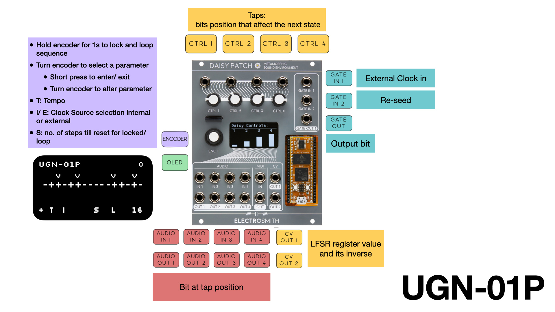
The UGN-01P is a patch prototype of UGN-01 module. It is a unit generator for both organized and random control voltages and gates. It is operationally simple but contains extensive potential for expression.
UGN-01 exposes the inner workings of a linear-feedback shift register, providing parametric control to tap positions, clock rate, and seed to allow musical exploration and expression across the different time scales of music.
Hey Jprecursor, I love your project idea, but I can’t seem to have access to a download link for it. Is there any other way to download than this “bit” button? it doesn’t seem to link me anywhere. Thanks!
@jprecursor , I have a minor suggestion if you don’t mind. Using inverted value as second CV output feels a bit wasteful - it’s easy to invert signal using common analog utilities. You could probably utilize it for something more interesting. For example, XOR current register value with previous, output LFSR using different endianness or do something else not easily done outside the module.
That bitwise invertion still means you’re outputting just pow(2, sizeof(LFSR)) - 1 - CV1. And the first value is a constant. So you’ll be getting something like this with 4 bit LFSR:
Binary CV1
Decimal CV1
Binary CV2
Decimal CV2
0000
0
1111
15
0001
1
1110
14
0010
2
1101
13
…
…
…
…
1110
14
0001
1
1111
15
0000
0
The same value can also be obtained by inverting CV1 and adding voltage produced for value 15, so it’s linearly depending on CV1.