Hi everyone, I’d like to introduce to you, the kxmx_nehcmeulb - An inverted kxmx_bluemchen.
It is essentially the same as the kxmx_bluemchen with a couple of important differences:
- MIDI in now MIDI out
- CV in is now CV out
- Audio in is now both Audio in and CV in
…otherwise it’s the same, oh and I inverted the panel colors to make it obvious 
These changes don’t affect the front PCB (or panel) at all, so if you already have a kxmx_bluemchen, you could just swap out the back PCB for this functionality.
The schematic and PCB layout are available here, and it’s also on ModularGrid
I don’t think I’ll be doing any DIY kits unless there is significant interest, but feel free to get in touch if you’d like one, perhaps we can work something out.
6 Likes
What peripherals do you have exposed on the panel? It would be super cool to daisy chain (no pun intended) multiple bleumchens and nehcuelbs via i2c or something.
I was very close to including select bus support, since I have a Rene MK2 and a Disting MK4 in my case, but decided against it because:
- I’ve never used it in the context of the modules I already have.
- The kxmx_bluemchen doesn’t have it, and I’d need a new hardware revision to support it.
- I’d need to somehow find time to write software to support it.
- The protocol is a pretty “how-ya-doin’”.
For interconnects over the front panel A uni-directional (nehcmeulb->bluemchen) MIDI/UART interconnect is a possibility. One could also increase the baud rate until the Opto-coupler stops playing along.
I’m not to familiar with the alt functions of the GPIO pins.
- CV_OUTs on the kxmx_nehcmeulb are connected to
PA4 and PA5
- CV_INs on both the kxmx_nehcmeulb and the kxmx _bluemchen are connected to
PA7 and PC4
A quick look through the pinout CSV file doesn’t give me any clever ideas.
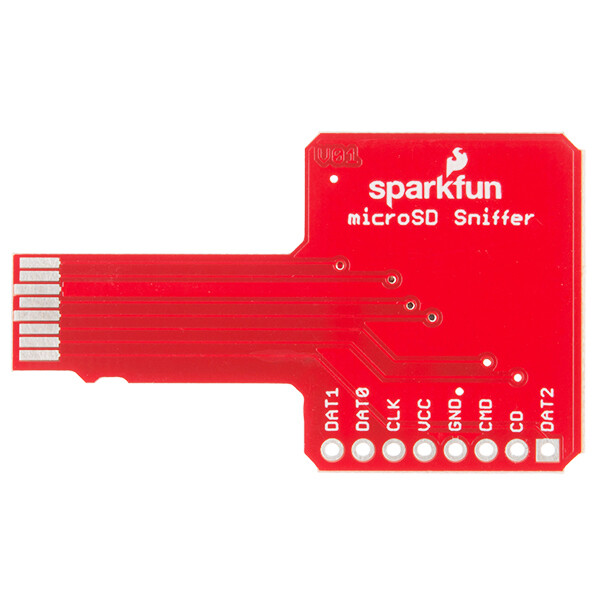
One final idea I’ve mulled over in the past, Using the SD card slot with a PCB like this:
…and a ribbon cable connection. This exposes PC11, PC10, PC9, PC8, PD2 and PC12, and would also be compatible with the Patch. Unfortunately, aside from UART3/4/5 there doesn’t seem to be a candidate peripheral, and nothing which would work as a multi-device bus.
I was picturing a pin header on the pcb itself, then you would connect the two modules via a jumper. Kinda like many eurorack modules do with expanders.
With the recent uart, i2c, etc. updates there’s a ton of peripherals to choose from, so there’s a good chance you have some combination of pins free you can use.
It should be noted you’ll have to dig into the files a bit to discover all of the peripherals available. They’re not all labeled on the seed pinout graphic since there’s really a ton.
Yeah, there would be a spot for some 0.127mm pitch SMT headers on the back PCB, but I can’t really route anything there on the current two layer PCB, the routing is just too tight.
A related thought experiment…
If one were to assume the role of master, and the other of slave, then it should be theoretically possible to attach two Daisy Seeds to each other via SAI_2 right? Assuming then that channels 3 and 4 AudioCallback of each Seed points at the other, then what is assigned to the out buffer of one Seed becomes available at the ‘in’ buffer of the other Seed, and vice versa, albeit with a delay of one block size. right?
If that is possible, there might be some really weird usefulness to be had from it. If the I2S signals don’t lose too much integrity over a ribbon cable, then I might just need to look into a four layer design.
I’ve never actually tried it, but I don’t see why that wouldn’t work! I’d refer to the patch schem + code to start playing with that.
I’d bet you could actually do audio over UART as well, using the front panel connection you mentioned.
Might be interesting.
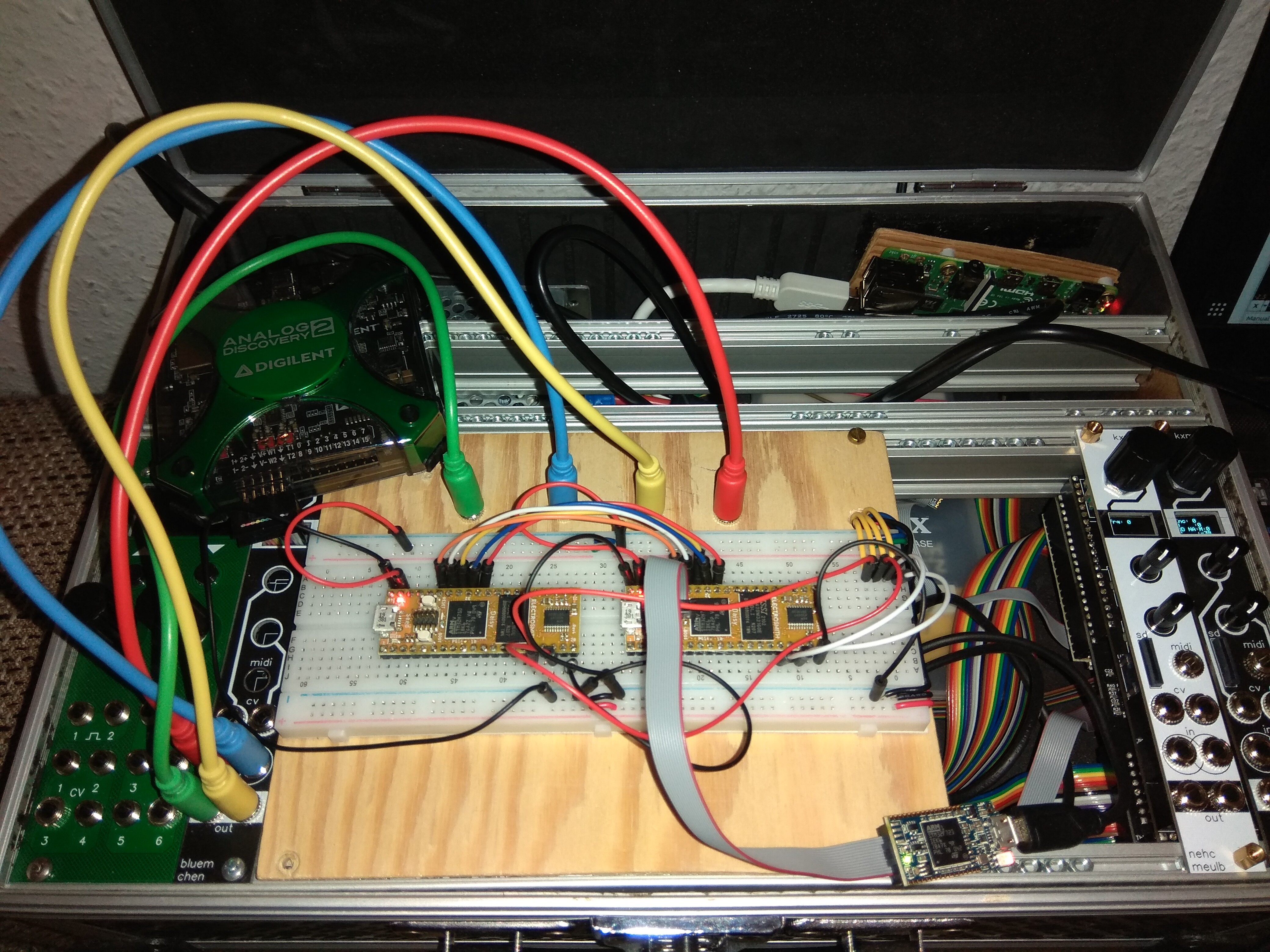
So I got a little time to give it a try, and it works, sort of…
I attached two seeds together…
…and flashed this program:
…and I was able to send a signal from my function generator to input 1 of the master Seed, pass it via SAI2 to the slave Seed and verify it with my scope on output 1 of the slave - Success!
What didn’t work is the same thing in reverse. A signal on input 1 of the slave seed does not get passed via SAI_2 back to the master. It is eminently possible that am missing something extremely obvious. This setup requires some mental gymnastics, what with them masters and slaves and transmits and receives and all…
Another thing I noticed, the slave seed does not always latch onto the master, but sometimes needed two or three resets to get in sync. This might be due to signal integrity, or some initialization expectations that aren’t being met. I didn’t take the time to probe the digital audio signals, my scope struggles with those speeds, and I’m not really sure what I’m trying to accomplish here anyhow.
All in all a fun little experiment… If you have a minute, browse my gist for any egregious errors. I’d like to verify it fully.
3 Likes
Veering off topic here but the idea of a multi-daisy powered mixing module / synth / FX thing gets me feeling all warm inside. 8 stereo inputs for starters…
/swoons

