I definitely will be doing something like this to monitor processor usage as soon as I learn to crawl. I think it will be not just useful, but almost necessary, when doing complex algorithms. Coming from the FV-1, I constantly had “cycle anxiety”, but it was explicit how many instructions I had left per sample.
I plan to use the metronome to turn off the Seed user LED once per second, accumulate the the cycle count during callbacks as described, and turn it on again proportional to the ratio of used cycles to the total 400M cycles per period. Simple programs will keep the LED on almost constantly. The one-second flash will get shorter and shorter as processor usage increases. I prefer this continuous “gas gauge” visual rather than a binary “warning light”. Should be easy, no? Maybe someone already has done it.
I am a little worried about @antisvin’s comment about SDRAM access being a potential limiter. One of my effects that I want to port and improve on from the FV-1 is a spring reverb. It now uses 40 allpass filters and some delays at 32KHz sample rate, and I would like to start with more than 100 at 48KHz to better model the spring’s frequency dispersion. I know that the Daisy processor is vastly more powerful, but I don’t know how efficient the allpass class in DaisySP will be. It will be a good benchmark for how much of a step up Daisy is from the FV-1.
Sounds cool! Please share the code if/when you finish it! I just wanted to detect if I was maxing out. Unfortunately I didn’t measure how much of my problem was due to my SDRAM access and how much was CPU usage…
Blockquote
The Oscillator class still uses the math.h sin function instead of some fast-approximation which could be pretty limiting depending on how-many you’re using and what waveform. You could sanity check that by switching them all to the naive square waveform and seeing if you’re still close. And you could run the LFOs at once per callback instead of once per sample, but then you’ll still have to filter or interpolate it to get smooth changes on most parameters.
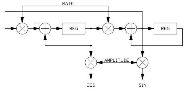
Wouldn’t it make more sense to do SIN/COS oscillators “DSP-style” like this:
I suspect that these might need to be implemented with integer math in order for their amplitude to be stable over time, and then converted to a float return value for use. Run once per sample as an audio-rate oscillator or once per callback as an LFO. This should be super-fast on this processor, right?
Some details of how to use an SVF as an oscillator are in Hal Chamberlin’s Musical Applications of Microprocessors book. This page has a good example of doing just that:
No @jaradical, I appreciate the great reference, and I think the OP, @StaffanMelin will too.
Yes, exactly what I am talking about. Basically a 2nd-order state variable filter with no input, infinite Q (0 damping), with initial conditions set to say 0 and 1. Interesting that they say that as an LFO it is stable with either fixed or floating point math, and at any amplitude. Given this, and that it is so ridiculously simple and efficient to implement, it makes sense to run at the sample rate rather than at the callback rate.
Indeed, both forms are actually the same and called “magic circle”. It is a stable oscillator, even at low frequencies and low numerical resolution. However both outputs are not in exact quadrature, there is half a sample delay, which becomes a significant error at high frequency but is probably not an issue for LFOs. There is also the Martin Vicanek’s oscillator, with two more operations but a very nice behaviour.
Thank you to all who wrote. Maybe it is time to implement an LFOOscillator class? I will see if I get the time to work on this because I really want to dig in a step further.
Previously, working on a low power Arduino, I’ve aproximated a SINE with a TRIangle!
Interpolating in lookup tables works pretty well for sines too. It’s pretty straight forward and I have some examples if you’re interested.
For other waveforms care must be taken to ensure they’re band limitted because you can quickly run into aliasing problems with the harmonics. One approach is to construct them from sines and only include the first handful of harmonics.
Another way, that I haven’t tried yet, is to oversample them, do digital filtering to remove unwanted harmonics and then downsample on output.
Another little trick I have used for generating octaves of sine waves for additive synthesis: Start with the SV fundamental oscillator, and then use the trig identity cos(2x) = 1 - 2 * [sin(x)]^2.
In other words, you can generate an octave-up sine (or cosine) wave by multiplying the oscillator output by itself, scaling it, and offsetting it back down. Do it again for 4x the fundamental, and again for 8x. Very simple and efficient!
OK, my very first working code. I stole from @Firesledge because he uses a hardware timer for his CpuLoadBlink, so it will accurately measure SDRAM access as well as processor cycles. He had the code spread over four files with proper C++ structure. I wanted to strip it down to the bare algorithm to get blinking and later create a proper class out of it when I get beyond kindergarten. I added this code to the Looper example on my pod:
t_prev = t_start;                   // save last start time
t_start = Timer.GetTick ();         // and get new one
// Put this at the end of the callback:
// Timer.DelayUs (800);              // Can add waste time for testing
t_finish = Timer.GetTick ();
t_clback = std::max(t_clback, t_finish - t_start);
ms_clback = (t_clback * 1000) / (t_start - t_prev)
if (ms_cntr++ == 1000)              // 1 sec blink rate at 48KHz, 48 samples
    {
    ms_cntr = t_clback = 0;
    pod.seed.SetLed(false);         //off to start
    }
if (ms_cntr == ms_clback)
    {
    pod.seed.SetLed(true);          //on when done
    }
It blinks with a period of one thousandth the callback rate, or once per second at the default 48KHz sample rate, 48 sample callback buffer size. The ON duty cycle is proportional to the time NOT in callback.
@donstavely, this time code is super useful! I’m porting code from Arduino, and looking for the libdaisy replacement for millis(); nice to have some working code to start from I did some cut-and-paste just to test, and wound up with this in Main:
I thought I was going to see time in milliseconds - these numbers are 100K times that. As a result, I’m seeing rollover very quickly; this will be hard to work with. Am I missing something here? Oh, and can someone tell me where the value of a “tick” is defined? Thanks!
You should probably use timer.GetFreq() to compute the time in s or ms from the timer.GetTick(). I don’t know why the GetMs() is implemented like this in libDaisy/src/per/tim.cpp (see below), but it doesn’t return what you could expect from its name or description.
millis: 6816314, tick: 13632831. freq: 200000000
time in seconds: 0.068164
millis: 56916312, tick: 113832825. freq: 200000000
time in seconds: 0.569164
millis: 107016317, tick: 214032837. freq: 200000000
time in seconds: 1.070164
millis: 157116317, tick: 314232837. freq: 200000000
time in seconds: 1.571164
Tick/freq seems to give time in secs (I’m guessing that the interval of 501 ms that I’m seeing between prints is 500ms for the delay, and 1 ms for the timer/print calls) Unfortunately ticks rolls over at about 21 secs. millis looks to be half of ticks. I dunno. Hopefully, one of the Electro-Smith folks will clarify this on Monday. In the meantime, I can cobble together something from this to proceed. Thanks again!
The timer ticks are stored as a 32-bit unsigned integer. So with a 200 MHz clock, the tick counter reaches 2^32 after 21 s and overflows. If you only need to measure short time periods, just subtracting two consecutive values is enough, overflow will be compensated automatically.
If you need the absolute time, you should run your own 64-bit accumulator and add the measured periods. This means you should keep checking the time within 21 s intervals. Or use a second, much slower timer to evaluate from how many 2^32 steps you should fix the newly read value.
Just browsing the STM32H750 Reference Manual - perhaps, if one is using an STLINK or similar it may be possible to use the JTAG DAP to access some of the trace infrastructure. Polling the ITM or ETM would give useful information where a program is spending its time. Of course, I haven’t tried using any of it, so I don’t have a firm idea of what’s possible. YMMV etc.
Yep! And fortunately, I’m measuring sequencer steps, so a few seconds will be “gracious plenty” as we say here! I had been thinking about using deltas, but my intuition led me astray; it is, indeed, as you say - the math works out and overflow is compensated automatically! For anyone else who might want to just grab code, here’s my final test code with output. Thanks for “talking me through it” @Firesledge
tick: 1903799931, delta time in ms: 501.000000
tick: 2003999931, delta time in ms: 501.000000
tick: 2104199935, delta time in ms: 501.000000
tick: -2090567361, delta time in ms: 501.000000
tick: -1990367365, delta time in ms: 501.000000
tick: -1890167367, delta time in ms: 501.000000