Hi,
in my current project I’m getting some weird noise when I start up an additional LFO. So I wonder if I have hit the roof, performance wise.
How can I measure this? I guess it is a matter of detecting whether the audio callback takes too long?
I saw @antisvin’s reply (The Daisy Roadmap) to the Road map, but I don’t understand it. I’m running C++ with libdaisy and DaisySP.
Many thanks in advance!
Staffan
What exactly is not clear? You have:
- known value of MCU cycles per second 400’000’000 (
ncpu)
- known sample buffer size (48 by default) (
bs)
- know number of samples per second (48000) (
sr)
- a register that counts how many MCU cycles passed
So you can count number of cycles that would be available for processing each buffer (total = ncpu * bs / sr). With default settings you should be able to use up to 400k cycles.
I’ve left some code for accessing DWT register on MCU that you’ve seen. You must unlock its debug mode to enable cycles measurement when when your patch starts. Then you’ll have to write 0 to the counter field when your audio callback starts and read new value from it just before exiting audio callback. This would give you the actual number of cycles spent processing audio which you can divide by total cycles to get CPU utilization ratio.
DWT register definition is in “core_cm7.h” header from CMSIS, it’s present in libDaisy.
2 Likes
Thank you @antisvin, worked like a charm! Very helpful!
(I understood the calculations, but not the technique, as I haven’t dived this deep into the MCU before.)
This is what I did in case anyone else need this.
Include
#include "core_cm7.h"
In main(), before starting the audio callback:
// setup measurement
CoreDebug->DEMCR |= CoreDebug_DEMCR_TRCENA_Msk;
DWT->LAR = 0xC5ACCE55;
DWT->CYCCNT = 0;
DWT->CTRL |= DWT_CTRL_CYCCNTENA_Msk;

// Start calling the audio callback
hardware.StartAudio(AudioCallback);
Then at the very top of my audio callback:
void AudioCallback(float* in, float* out, size_t size)
{
	// variable declarations here -- removed

	// measure - start
	DWT->CYCCNT = 0;
And right before exiting the audio callback I check the value and turn on the LED if I’m near the limit:
// measure - stop
if (DWT->CYCCNT > 390000)
	hardware.SetLed(true);
This corresponded with me getting audio artefacts (noise). The value (390 000) should be computed according to @antisvin’s clear listing. Right now I only wanted to know if I was maxing out the processor.
Once again, thanks!
4 Likes
Good to know that you’ve got it working!
I would say that maxing out processor is not necessary the reason - it can be caused by too much SDRAM access, for instance. This happens frequently for certain DSP code (reverbs, phys. modeling).
1 Like
Yeah, I have some delaylines in SDRAM…I will look into that. But I broke the 390K barrier by starting up a bunch of LFOs. I am using the Oscillator class for that, maybe I can use something smarter. Or rather, maybe call my lfo.Process()'s less often, say every 10th CB?
You can use the same approach to measure various sections of your code to nail down what exactly is using the most time.
The Oscillator class still uses the math.h sin function instead of some fast-approximation which could be pretty limiting depending on how-many you’re using and what waveform. You could sanity check that by switching them all to the naive square waveform and seeing if you’re still close. And you could run the LFOs at once per callback instead of once per sample, but then you’ll still have to filter or interpolate it to get smooth changes on most parameters.
And if you haven’t you could can always boost the CPU to 480MHz for a bit of cpu headroom.
1 Like
That is good advice! I could probably do with a triangle wave for LFO.
But I am still amazed by the Daisy Seed performance. Right now I’ve got:
7 x synth tracks with filters, adsr, delay, lfo (filter cutoff), reverb send
1 x drum track with 2 osc’s doing pitch and amp envelopes, 4 noise gen’s running filter and adsr, reverb send
1 x mixer that pans and “gains” all tracks AND sends an adjustable amount to a global reverb
all controlled by a sequencer controlled by the Metro class.
Awesome!!!
1 Like
Right now I am running them every 10th sample, it made a difference.
Or someone could can give everyone a free CPU upgrade finally  No problems noticed while running on stock frequency for last few months on OWL.
I definitely will be doing something like this to monitor processor usage as soon as I learn to crawl. I think it will be not just useful, but almost necessary, when doing complex algorithms. Coming from the FV-1, I constantly had “cycle anxiety”, but it was explicit how many instructions I had left per sample.
I plan to use the metronome to turn off the Seed user LED once per second, accumulate the the cycle count during callbacks as described, and turn it on again proportional to the ratio of used cycles to the total 400M cycles per period. Simple programs will keep the LED on almost constantly. The one-second flash will get shorter and shorter as processor usage increases. I prefer this continuous “gas gauge” visual rather than a binary “warning light”. Should be easy, no? Maybe someone already has done it.
I am a little worried about @antisvin’s comment about SDRAM access being a potential limiter. One of my effects that I want to port and improve on from the FV-1 is a spring reverb. It now uses 40 allpass filters and some delays at 32KHz sample rate, and I would like to start with more than 100 at 48KHz to better model the spring’s frequency dispersion. I know that the Daisy processor is vastly more powerful, but I don’t know how efficient the allpass class in DaisySP will be. It will be a good benchmark for how much of a step up Daisy is from the FV-1.
Sounds cool! Please share the code if/when you finish it! I just wanted to detect if I was maxing out. Unfortunately I didn’t measure how much of my problem was due to my SDRAM access and how much was CPU usage…
I’ve done exactly the same thing when I received my Daisy!
My code is here. Usage is simple. Create the probe in the global section with a custom function indicating how you want to light your LED:
#include "dzy/CpuLoadBlink.h"
#include "daisy_seed.h"

daisy::DaisySeed hardware;
struct LedLight {
	void operator () (bool light_flag) { hardware.SetLed (light_flag); }
};
dzy::CpuLoadBlink <LedLight> cpu_load;
In your init (main) function:
hardware.Configure();
hardware.Init();
const auto fs = hardware.AudioSampleRate ();
cpu_load.set_sample_freq (fs);
hardware.StartAudio (audio_callback);
In your callback function:
void audio_callback (float *src_ptr, float *dst_ptr, size_t bufsize)
{
	cpu_load.blk_beg ();
	const int nbr_spl = int (bufsize >> 1); // Nb of stereo frames

	// Do stuff...

	cpu_load.blk_end (nbr_spl);
}
1 Like
@shensley wrote:
Blockquote
The Oscillator class still uses the math.h sin function instead of some fast-approximation which could be pretty limiting depending on how-many you’re using and what waveform. You could sanity check that by switching them all to the naive square waveform and seeing if you’re still close. And you could run the LFOs at once per callback instead of once per sample, but then you’ll still have to filter or interpolate it to get smooth changes on most parameters.
Wouldn’t it make more sense to do SIN/COS oscillators “DSP-style” like this:
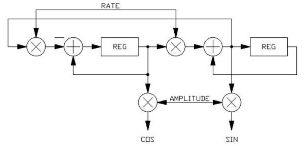
I suspect that these might need to be implemented with integer math in order for their amplitude to be stable over time, and then converted to a float return value for use. Run once per sample as an audio-rate oscillator or once per callback as an LFO. This should be super-fast on this processor, right?
1 Like
Sorry to hijack the thread:
Some details of how to use an SVF as an oscillator are in Hal Chamberlin’s Musical Applications of Microprocessors book. This page has a good example of doing just that:
https://www.earlevel.com/main/2003/03/02/the-digital-state-variable-filter/
Which I think is the exact same thing @donstavely is talking about.
Cheers
1 Like
No @jaradical, I appreciate the great reference, and I think the OP, @StaffanMelin will too.
Yes, exactly what I am talking about. Basically a 2nd-order state variable filter with no input, infinite Q (0 damping), with initial conditions set to say 0 and 1. Interesting that they say that as an LFO it is stable with either fixed or floating point math, and at any amplitude. Given this, and that it is so ridiculously simple and efficient to implement, it makes sense to run at the sample rate rather than at the callback rate.
1 Like
Indeed, both forms are actually the same and called “magic circle”. It is a stable oscillator, even at low frequencies and low numerical resolution. However both outputs are not in exact quadrature, there is half a sample delay, which becomes a significant error at high frequency but is probably not an issue for LFOs. There is also the Martin Vicanek’s oscillator, with two more operations but a very nice behaviour.
1 Like
Thank you to all who wrote. Maybe it is time to implement an LFOOscillator class? I will see if I get the time to work on this because I really want to dig in a step further.
Previously, working on a low power Arduino, I’ve aproximated a SINE with a TRIangle! 
Interpolating in lookup tables works pretty well for sines too. It’s pretty straight forward and I have some examples if you’re interested.
For other waveforms care must be taken to ensure they’re band limitted because you can quickly run into aliasing problems with the harmonics. One approach is to construct them from sines and only include the first handful of harmonics.
Another way, that I haven’t tried yet, is to oversample them, do digital filtering to remove unwanted harmonics and then downsample on output.
Cheers
1 Like
Another little trick I have used for generating octaves of sine waves for additive synthesis: Start with the SV fundamental oscillator, and then use the trig identity cos(2x) = 1 - 2 * [sin(x)]^2.
In other words, you can generate an octave-up sine (or cosine) wave by multiplying the oscillator output by itself, scaling it, and offsetting it back down. Do it again for 4x the fundamental, and again for 8x. Very simple and efficient!
1 Like
OK, my very first working code. I stole from @Firesledge because he uses a hardware timer for his CpuLoadBlink, so it will accurately measure SDRAM access as well as processor cycles. He had the code spread over four files with proper C++ structure. I wanted to strip it down to the bare algorithm to get blinking and later create a proper class out of it when I get beyond kindergarten. I added this code to the Looper example on my pod:
// All globals for now:
uint32_t            t_start = 0;        // Added vars for counting
uint32_t            t_finish = 0;
uint32_t            t_clback = 0;
uint32_t            t_prev = 0;
uint32_t            ms_cntr = 0;
uint32_t            ms_clback = 0;
TimerHandle Timer;                   // Add timer object (assumes namespace daisy)
// Put this in Main before starting the callback:
Timer.Init (TimerHandle::Config {
             TimerHandle::Config::Peripheral::TIM_2,
             TimerHandle::Config::CounterDir::UP});
Timer.Start ();
// Put this at the beginning of the callback:
t_prev = t_start;                   // save last start time
t_start = Timer.GetTick ();         // and get new one
// Put this at the end of the callback:
// Timer.DelayUs (800);              // Can add waste time for testing
t_finish = Timer.GetTick ();
t_clback = std::max(t_clback, t_finish - t_start);
ms_clback = (t_clback * 1000) / (t_start - t_prev)
if (ms_cntr++ == 1000)              // 1 sec blink rate at 48KHz, 48 samples
    {
    ms_cntr = t_clback = 0;
    pod.seed.SetLed(false);         //off to start
    }
if (ms_cntr == ms_clback)
    {
    pod.seed.SetLed(true);          //on when done
    }
It blinks with a period of one thousandth the callback rate, or once per second at the default 48KHz sample rate, 48 sample callback buffer size. The ON duty cycle is proportional to the time NOT in callback.
2 Likes