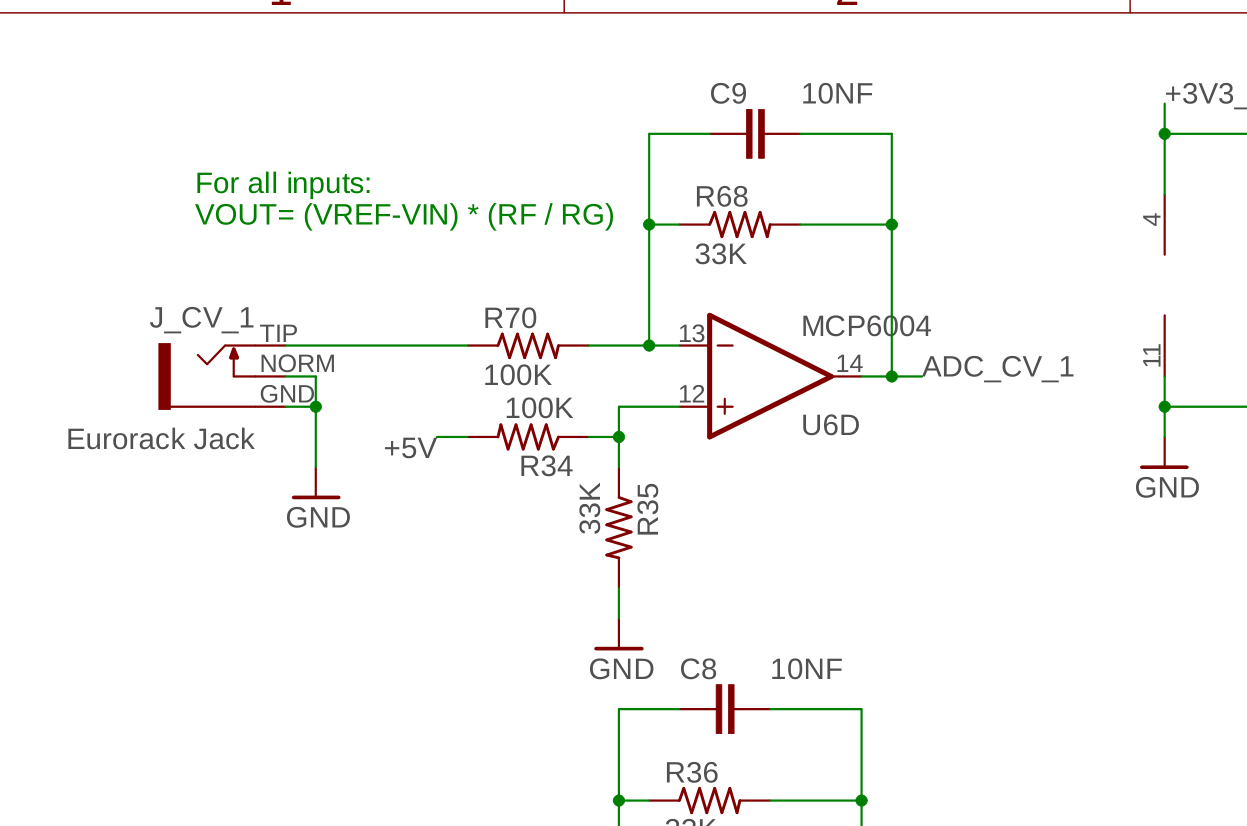
I’m trying to breadboard an ADC CV input for my current project and am using the one from the Daisy Field schematic as a reference.
I have two questions about this:
-
What are the input/output voltage levels here? Are they the same as on the Daisy Patch (-5V to +5V in, 0V to +3.3V out)?
-
Which resistors correspond to RF and RG in the equation in the above screenshot? And is VREF here +5V, or is it the reduced voltage going into the positive input of the op amp?