This is some sort of simple and crude, but perhaps it might still be inspiring or useful for others?
What is it?
The idea is to provide a simple means of output on a Oled Display for Puredata Patches and use the Programming invironment of Plugdata. Also a simple menue interface to set parameters with a rot encoder is shown.
How is it done?
We can think of 3 components of the running software:
A The callback routine triggered by interrupt every millisecond.
A1 The Plugdata patch, compiled by heavy for sound processing is running in A.
B The main loop, which will be interrupted by A for less time critical stuff. Here we will process the display handling.
To have a very simple means for communication we use a plugdata table (tabwrite and tabread), which can be accessed as an array of floats from B-side.
Hardware connections:
Hardware connection of a 128*64 pixel monocrome display with SSD1306 controller via I2C.
VCC goes to 3V3_digital Pin 38
GND goes to GND_digital Pin 40
I2C SCL Pin 12
I2C SDA PIN 13
I2C address = 0x3C
The display is not included in the JSON file, because we only handle the it on B-side. The pins are somewhere fixed to these pins. Setting different pins did not work! The speed works with 400kHz in my setup.
The rot-encoder is connected to the pins as described in the JSON file:
   "encoder": {
      "component": "Encoder",
      "pin": {
         "a": 26,
         "b": 25,
         "click": 14
      }
The numbers are digital port numbers here.
Software setup:
We have to tell Plugdata, that we want to include some user software. Fortunately this is quite straightforward, because plugdata uses a template file HeavyDaisy.cpp, which we can modify. It can be found in:
……\plugdata\Toolchain\usr\bin\Heavy_internal\hvcc\generators\c2daisy\templates
Here we add some lines to include the user source code file, and to install the CpuLoadMeter, to call userMainInit(); and to call userMainLoop();
Then we write a source code file which contains the 2 routines userMainInit() and userMainLoop().
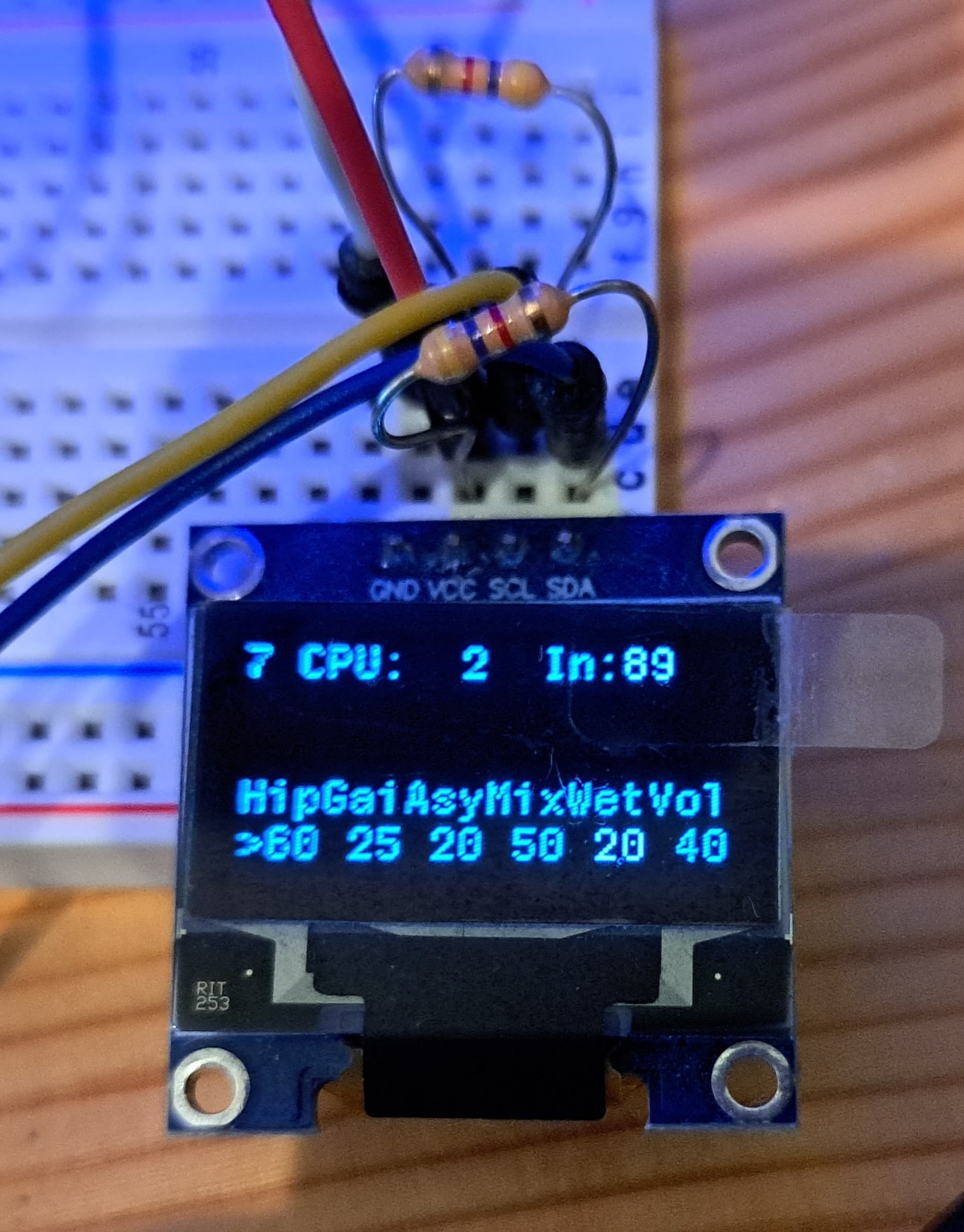
The Encoder Press switch cycles through the parameters to be edited. The parameter number is at table position 48, the rot encoder can then change the selected parameter.
Example:
The example displays the CPU load and an input level (position 6/7 of the table). CPU load of the callback routine in percent.
Also as a parameter number 5 at position 60 of the table, the volume of the output can be controlled.
There is also a blinking led, using the table.
I had difficulties to get the tabread/tabwrite do what I wanted and I was not able to find in depth discriptions. It seems that tabread needs a bang to read. And tabwrite needs both an address with bang and new data with bang for every write.
For easy display, I use 0…100 pc for all parameters, shown as 0…99 with 2 digits. This way I can squeeze 6 parameters in one line.
With included debug printing, this patch can be compiled with “big” patch size.
THANKS
Big thanks for Daisy and for PLUGDATA and the help I got here in the forum!!!
Have fun, Christof
Aaaaaah, this is ???: I cannot upload a ZIP file. Is there a trick? Renaming for jpg did not work… How are you supposed to provide examples???