It doesn’t look like the pinout for Rev 7 is available online in CSV format.
This csv still references an old codec. The chip that I have has the PCM3060 and I am unsure which pins the I2C are connected to or even which I2C instance it is (hi2s1, 2, 3?).
I am developing using CubeIDE, can you please provide more information & ideally the schematic on the latest revision so I can understand the hardware configuration in more detail.
Thank you, I discovered that the PCM3060::Init seems to only be relevant to the Daisy Patch.
Daisy seed seems to simply pull down the DeEmp pin in software. Whats interesting is when I probe that pin, this pin is not tied to the STM32 Pin B11 as the daisy_seed.cpp file suggests.
I believe the configuration is fixed and not configurable. I am going to ignore the configuration now and proceed with getting audio pass through. Thanks!
As an aside, is there any intetion to release the schematics for Rev 7?
I think you may be misreading daisy_seed.cpp ; I may be also, of course. Anyway, your comment on PCM3060::Init is probably referrring to patch_sm, which is different from Patch. (confusing, yes?)
Looks to me like the Seed Rev 7 board takes the default in DaisySeed::ConfigureAudio(), which calls the poorly-named Ak4556::Init(). This function toggles B11, which is connected to reset on the earlier seed with 4556 codec. . What’s not clear to me is whether B11 is connected to the 3060 in any way on Rev 7, maybe B11 goes to the RST pin on the 3060? My guess is that the pcm3060 deemphasis pin is hardwired LOW on Seed Rev 7. I don’t have a scope handy to probe these pins.
To summarize, my impression is that the Rev7 board uses the pcm3060 in Hardware mode (meaning, no I2C or SPI configuration), with de-emphasis filter DISABLED.
Daisy documentation is spotty - and the question of when a reference schematic for Rev 7 will be provided has gone unanswered before.
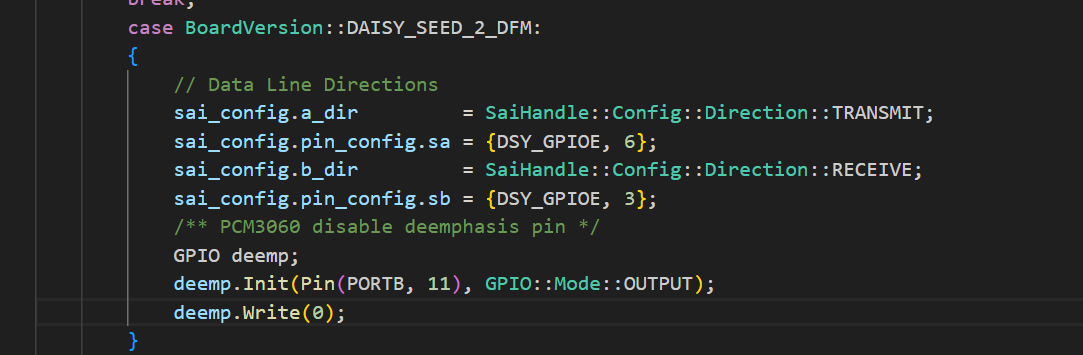
Interesting, it looks to me as though Rev 7 declares the board version (through the use of GPIO reads) as “DAISY_SEED_2_DFM”, which means that it doesn’t init the AK4556, but runs this function.
I understand that, but my comment was not discussing rev6. The comment above suggests that the rev7 schematics are out, but they are not. The breakout board schematics are out. It is misleading.
If there are any questions related to developing with the Daisy Seed that the published schematic does not answer, we will be more than happy to answer them and update our technical documentation accordingly.
Yup, there are! Hope you can help me.
I’m going to use the Daisy Seed for a quite different application (a Software Defined Radio), as it is a nice small dev board with a good MCU.
Due to this, I’m not:
Using libDaisy (I have a large C codebase, and don’t need any of its functionality)
Using the STM32H7 HAL, rather the LL or direct register manipulation, both for code size and efficiency.
I have successfully set up and used both the FMC for the SDRAM and the QSPI for the FLASH (I need them available before main() is invoked), and it seems that the old schematics I have actually matches my board in this respect.
Now, the Github repo with hardware documentation is fully 404 (why? it doesn’t look like there’s much to the DS HW that needs secrecy!), and the connection of the PCM3060 can only be partially inferred form the libDaisy code.
How is the onboard PCM3060 connected (if at all, apart from the obvious SAI1) to the STM32H750?
If it’s used in the simplified “HW mode”, what is the hardwired configuration?
From libDaisy code, I gather that PD4 is now grounded, instead of PD3 for V1.1, to allow for detection of the new revision.
Are there other changes to the schematics that needs to be highlighted?
What is the reason to publish only a partial schematic?
The availability of the HW documentation was one of the reason to invest in the platform, for me.
Hi,
one further suggestion for improvement would be to bring in the information, that the onboard LED is connected to D31. It would be good to have that on both the datasheet and the “schematic”. Oh, and while I am looking at the “schematic”, I see, that the Dx numbers are not there. Perhaps insert the pinout diagram there too or have it at a second page?
Christof
Actually a real documentation on HW would benefit us all.
The platform is interesting for a number of Digital Signal Processing application that go beyond the use for music and having the possibility to use the Coded at full extent would make development much easier.
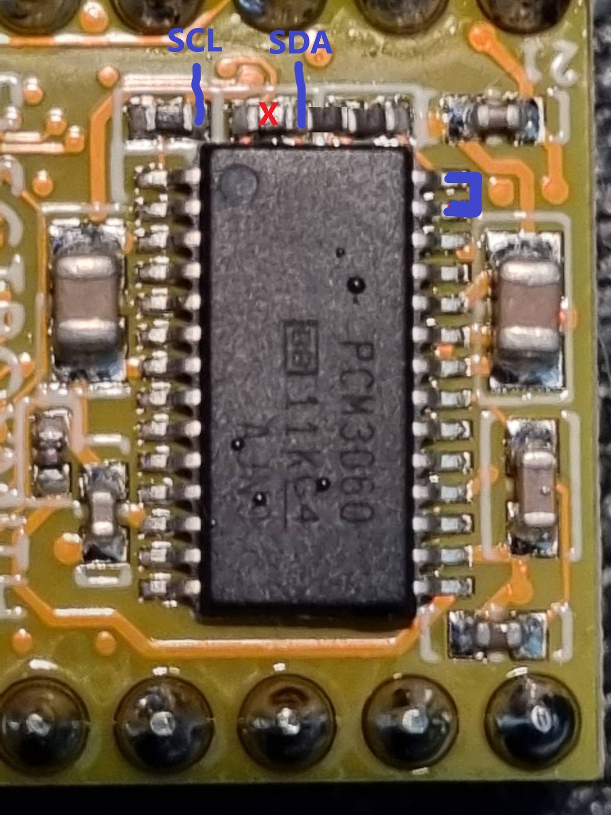
By playing with the multimeter I have verified that pcm3060 pin 2 is neither hardwired to GND nor to Vdd.
If you run the Blink test that pin is forced to zero, this indicates that it’s tied to some logic.
If you run a test not using libDaisy the pin is at one, so it’s libDaisy that can handle that pin. → Not true! See Errata below
Now if you hack the Blink code for moving the PB11 following the blink, pcm3060 pin 2 doesn’t toggle, it remains at zero.
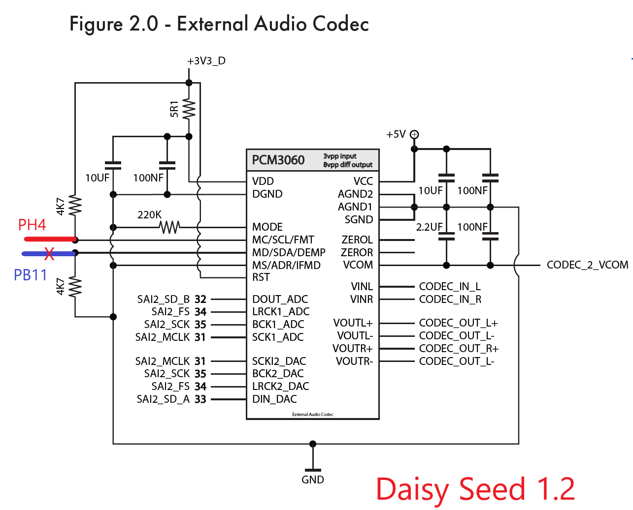
Interesting is that if you move PH4, you can verify that pcm3060 pin 1 toggles, meaning that it’s connected.
That’s interesting as same as DAISY_SEED_1_1 we have i2c_config.pin_config.scl = {DSY_GPIOH, 4};
If PB11 was connected to pcm3060 pin 2 we would also have i2c_config.pin_config.sda = {DSY_GPIOB, 11};
Anyone can help understaing if pcm3060 pin 2 is really tied to PB11 and how?
Errata: pin 2 is fixed at zero all the time, even though it’s not directly connected to GND
Thanks for your post!
And welcome to the community. As an amateur radio enthusiast (KN6TAU), your project is really exciting to me!
We have added a page to the datasheet which should answer your questions about the internal audio codec - check out page 12 and let us know if anything is missing.
I understand your frustration about the hardware GitHub repo and schematic changes.
We did not come to this decision lightly and will do everything we can to improve the user experience within the new documentation paradigm.
Hi Andrew.
thanks for updating the datasheet, it helps a lot understanding.
Actually my Daisy Seed 1.2 has a different scheme, what I’ve found is this:
The scheme is not compliant with libDaisy as PB11 is not connected, but PH4 is.
It would be great if you may update the documentation but it would be even better
if you consider making a couple of very little changes to the board so that the connection to PB11 is restored, the connection to PH4 is kept and you add a jumper
between pin 27 and 28 of the codec, normally open, so that it’s possible to set
the codec to I2C mode.
The it’s still possible to make it on the existing PCB like that:
The Pull-down resistor on Pin 2 is removed and a Pull-up resistor is soldered
between the hot terminal of the Pullup resistor for MODE and the free terminal,
in order to use the I2C mode a shortcut between pin 27 and 28 of the codec is needed
and the SDA/SCL termination can be connected to pin 15 and 14 of the Daisy, but is such case I2C4 is to be used instead of I2C2.