Hey @sam !
I’ve only just got to the stage of designing the physical module so I’m not sure yet which board i’ll use.
If you don’t specify a board in your erbui file then the default board is used.
It has like 128 digital/analog inputs/outputs, so that’s a way to start when you don’t have a precise idea and you are first focusing on what the product should do (rather than how it will be produced).
When getting to hardware, you have only two choices for now: the kivu12 12HP board and the custom boards.
Since the custom-board is a new feature, just to be sure I put more context:
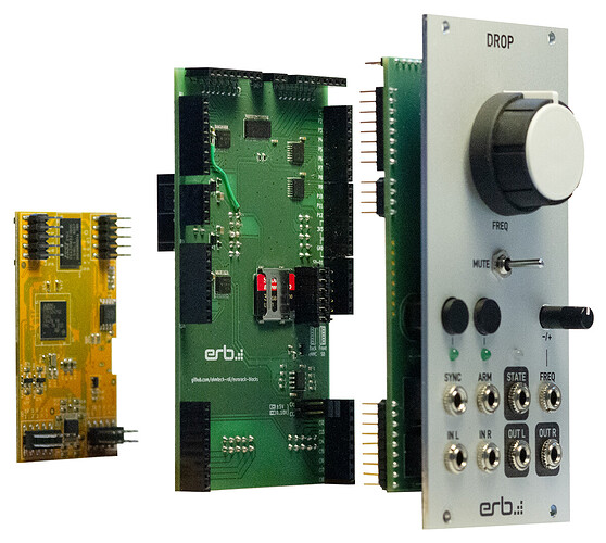
The kivu12 is a back board that is made to be reused from one front pcb to another and is depicted here in the middle:
The pin headers/sockets on the borders are placed so that they don’t get into the way of your components for generic layouts.
Given this view, what does the “custom-board” system is to “merge” the back board and the front pcb into one PCB:
- There is no more headers so more freedom to route what you want, at the expense of having to put the Daisy Patch Submodule yourself (see screenshot at the end of this message)
- The board can’t be reused for another module unless the other module has the same component layout (which Noise engineering did for the Versio series for example)
- The board can be massively produced
If there were an encoder implemention, I would gratefully utilise it but obviously don’t worry too much about me
All good, I was thinking adding it also, but the question is mainly when 
For now please one button (like tl1105) for encoder up and another for encoder down. The encoder will basically be that, and the Encoder implementation will return an increment.
Of course, I would be very interested in an online video course of the project.

I’m trying to make the Reverb module as a practice at the moment and I think there are a few moments in the process when a video tutorial would help a lot.
Could you please recall those moments so I could improve the project? The installation in this project is quite massive and I can totally picture people stopping in the middle of it.
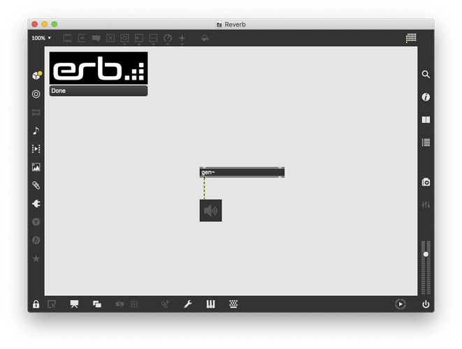
I’m stuck at the moment because I can’t make the Reverb module show up in VCV rack. I’ve saved the max patch but it doesn’t show up in the Library.
Here I think there would be a few things to check:
- Please open the Max console, save again to trigger build, and send me the content of the Max log (I want to check for any error)
- Do the same with the Rack logs, it’s in your
~/Documents/Rack/log.txt
The only other question I have is - When designing the front panel. Are there any rules for how inputs/ outputs/ buttons/ knobs, etc must be laid out? For example, must the inputs/outputs be at the bottom of the module? I’m not trying to do anything crazy but I don’t want to accidentally make an impossible design.
I guess there are no strong rules, everything is about usability. For example sequencers tends to have their jack connectors on the top of the modules, and all other modules tends to have their connectors on the bottom, simply for cable management (you tend to put sequencers at the bottom of your rack, closer to your body).
Remember to leave enough space between knobs, as you need to be able to put a finger between two knobs so you can touch one knob but not the other.
On this actually we plan to recreate some sort of VCV Rack in 3D with a virtual hand with fingers, so people could ensure everything is correct, because this also depends on the knob height and shape. But that’s another big project 
There are however physical constraints you need to comply with: components need to not collide.
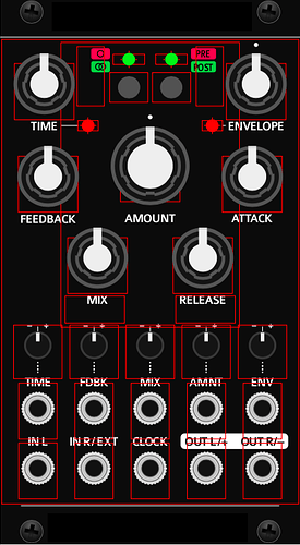
For this I designed controls in Illustrator so that you can see the footprint on the PCB to avoid collision.
I think I’ll add it in an extras folder to help with design. What do you think?


