Oopsy & Daisy Seed : hardware mapping

Yes that’s the general idea.

I tried your JSON here, and (other than weird formatting issues from the forum post) it generates good looking code AFAICT. I also compared it to the basic DaisySeed Knob example (https://github.com/electro-smith/DaisyExamples/blob/master/seed/Knob/Knob.cpp) and it looks quite comparable. I’m not sure why this wouldn’t be working, it all looks good from here.

Here’s the JSON formatted for anyone following along:

{
	"defines": {
	  "OOPSY_TARGET_SEED": 1
	},
	"labels": {
	  "params": {
		"knob1": "kn1",
		"knob2": "kn2",
		"knob3": "kn3"
	  },
	  "outs": {},
	  "datas": {}
	},
	"inputs": {
	  "kn1": {
		"automap": true,
		"code": "hardware.seed.adc.GetFloat(0);"
	  },
	  "kn2": {
		"automap": true,
		"code": "hardware.seed.adc.GetFloat(1);"
	  },
	  "kn3": {
		"automap": true,
		"code": "hardware.seed.adc.GetFloat(2);"
	  }
	},
	"outputs": {},
	"datahandlers": {},
	"inserts": [
	  {
		"where": "init",
		"code": "AdcChannelConfig cfg[3];"
	  },
	  {
		"where": "init",
		"code": "cfg[0].InitSingle(oopsy::daisy.hardware.seed.GetPin(21));"
	  },
	  {
		"where": "init",
		"code": "cfg[1].InitSingle(oopsy::daisy.hardware.seed.GetPin(22));"
	  },
	  {
		"where": "init",
		"code": "cfg[2].InitSingle(oopsy::daisy.hardware.seed.GetPin(23));"
	  },
	  {
		"where": "init",
		"code": "oopsy::daisy.hardware.seed.adc.Init(cfg, 3);"
	  },
	  {
		"where": "header",
		"code": "#include \"daisy_seed.h\""
	  },
	  {
		"where": "header",
		"code": "using namespace daisy;"
	  }
	],
	"max_apps": 1
}

The generated code looks like this:


#define OOPSY_TARGET_SEED (1)
#define OOPSY_IO_COUNT (2)
#include "daisy_seed.h"
using namespace daisy;
#include "../genlib_daisy.h"
#include "../genlib_daisy.cpp"
#include "../../graham/custom_2dtest.cpp"

struct App_custom_2dtest : public oopsy::App<App_custom_2dtest> {
	float gen_param_knob1;	
	void init(oopsy::GenDaisy& daisy) {
		daisy.gen = custom_2dtest::create(daisy.hardware.seed.AudioSampleRate(), daisy.hardware.seed.AudioBlockSize());
		custom_2dtest::State& gen = *(custom_2dtest::State *)daisy.gen;
		daisy.param_count = 1;
		gen_param_knob1 = 0.f;
	}

	void mainloopCallback(oopsy::GenDaisy& daisy, uint32_t t, uint32_t dt) {
		Daisy& hardware = daisy.hardware;
		custom_2dtest::State& gen = *(custom_2dtest::State *)daisy.gen;
	}

	void displayCallback(oopsy::GenDaisy& daisy, uint32_t t, uint32_t dt) {
		Daisy& hardware = daisy.hardware;
		custom_2dtest::State& gen = *(custom_2dtest::State *)daisy.gen;
	}

	void audioCallback(oopsy::GenDaisy& daisy, float **hardware_ins, float **hardware_outs, size_t size) {
		Daisy& hardware = daisy.hardware;
		custom_2dtest::State& gen = *(custom_2dtest::State *)daisy.gen;
		float kn1 = hardware.seed.adc.GetFloat(0);
		gen_param_knob1 = (float)(kn1*1.f + 0.f);
		gen.set_knob1(gen_param_knob1);
		float * dsy_in1 = hardware_ins[0];
		float * dsy_in2 = hardware_ins[1];
		float * dsy_out1 = hardware_outs[0];
		float * dsy_out2 = hardware_outs[1];
		// in1:
		float * inputs[] = { dsy_in1 }; 
		// out1:
		float * outputs[] = { dsy_out1 };
		gen.perform(inputs, outputs, size);
		memcpy(dsy_out2, dsy_out1, sizeof(float)*size);
	}	
};

// store apps in a union to re-use memory, since only one app is active at once:
union {
	App_custom_2dtest app_custom_2dtest;
} apps;

oopsy::AppDef appdefs[] = {
	{"custom_2dtest", []()->void { oopsy::daisy.reset(apps.app_custom_2dtest); } },
};

int main(void) {
	oopsy::daisy.hardware.Init(); 
	oopsy::daisy.hardware.seed.SetAudioSampleRate(daisy::SaiHandle::Config::SampleRate::SAI_48KHZ);
	AdcChannelConfig cfg[3];
	cfg[0].InitSingle(oopsy::daisy.hardware.seed.GetPin(21));
	cfg[1].InitSingle(oopsy::daisy.hardware.seed.GetPin(22));
	cfg[2].InitSingle(oopsy::daisy.hardware.seed.GetPin(23));
	oopsy::daisy.hardware.seed.adc.Init(cfg, 3);
	// insert custom hardware initialization here
	return oopsy::daisy.run(appdefs, 1);
}
2 Likes

Just to rule out hardware, it’s worth mentioning that one common issue when doing things with the Seed outside of a breakout board is to forget to connect the AGND pin to the DGND pin. This would result in the ADC pins not reading correctly (or at all).

Hi, thanks for your answers and sorry for the late reply (the notifications got filtered by my inbox).
My hardware configuration seemed OK, as I can run my code using the “patch” target and the first two ADC pots respond correctly, so I went back to try the “Osc” seed example again and found out my (stupid) mistake: my JSON was using the pin numbers corresponding to the actual hardware pins and not the “libDaisy” pins ! So the first ADCs would be 15 and 16 and not 22 and 23 (I actually got that wrong by 1 in my first JSON map too).
All is good now, some pot behaviour seems reversed compared to the “patch” target but I can easily switch that around on the breadboard. Only issue now is getting a clean decoupled 5v to the analog parts of my circuit, I’m waiting on an isolated DC/DC converter to try and reduce digital noise (saw this in another post in the forum, and on the “petal” schematics).
Thanks for your help, I’ll be more than happy to beta test more aspects of the custom seed Oopsy target as it progresses !

I’m getting to work on a Terrarium JSON this week.
Apparently PedalPCB has plans for another two or three Daisy boards “coming soon”
SO MANY THINGS!!!

/edit: found the Terrarium pin out out Github

1 Like

Hey sorry, having a beginners question -

i’d like to map the pod encoder’s value to a (for example) selector object in gen~. Means, everytime when i switch encoder there’s value x + 1, or x - 1 incoming to the selector and switching between the inputs
i tried using latch with the accum object but unfortunately couldn’t get any useful results.
thanks!

Hi Sandro,

[param encoder] should give you +1 or -1 signal when the encoder is turned. There is a gotcha here though: because the analogue inputs are sampled at block rate (normally 48 samples), that will actually result in a step function. To get a single-sample trigger out of it, you could route with a [change] into [eqp] like this:

Screen Shot 2021-01-23 at 10.00.10 AM

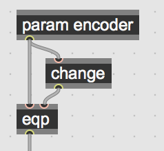
[eqp] is short for “equal-pass”: the input passes through if both inlets are equal, else it passes zero. [change] reports 1 when the input is rising, -1 when falling, and zero otherwise. So, in the frame that the [param encoder] step function goes from 0 to 1, the change also does the same, and eqp passes 1 through. In the next frame, the step function is flat, the [change] outputs zero, and thus so does [eqp]. And vice versa for -1.

Perhaps I should make an abstraction for this in oopsy, it’s likely a common need.

Then, routing this into a [+=] or [accum] (they are the same object, just different names) will give you an ‘endless encoder’ kind of value. The 2nd inlet of [+=] will reset the value to zero.

Great! exactly what i’ve been looking for, and thanks for the good explanation - yesterday i achieved some success by: param encoder - /50 - and feeding it into the accum object - round. but unfortunately i just could step up and not down - finally i know the right way:D but anyway learned so much by figuring out this problem!

sorry, one more question: in theory backwards movement should be recognized by change and giving us -1, this going to accum should substract 1, and make a step back, yes? i’m asking cause my encoder just puts out +1, means i can only step forward not backward, did i miss something to add backwards stepping? best and thanks

Yes, it should. It looks like there’s a bug in Oopsy here – let me get that fixed up.

OK just pushed a fix to the main branch in git. If you don’t want to do the git thing, the fix is very simple:

  1. Change [param encoder] to [param encoder @min -1 @max 1]
  2. Edit the /source/daisy.pos.json file on line 49

from:
"getter": "(hardware.encoder.Increment())"

to:

"getter": "(hardware.encoder.Increment()*0.5f+0.5f)"

2 Likes

great! will try it out later, thanks for the support :smiley:

hello! i’m in the process of puzzling custom breadboard setups for my daisy seeds, and i’m starting to hit my head on what i can do with the “petal” target in oopsy. have you made any progress with your project, lobster?

Hey,
I got my project working the way I wanted by creating a custom JSON file as Graham pointed out above, he made a nice clear wiki about how you can do that here: Custom Seed Targets · electro-smith/oopsy Wiki · GitHub.

I haven’t really messed around with settings other than mapping knobs and switches yet (I’m trying to figure out other aspects of my electronics design), but starting from the custom JSON example and cross-referencing that with Daisy C++ examples that include what you’re trying to do should be quite easy, you just need to figure out where the JSON dicts insert code into the oopsy-generated C++.

2 Likes

hey! i’ve been puzzling after this for a while now, and while the daisy examples are well-documented enough for someone who has experience with C++, they’re not entirely legible to me. maybe i’m missing something major, but i can’t find anywhere in any of the github repositories how to use the code.

can you tell me where to find a reference to understand your JSON file? specifically what the

AdcChannelConfig cfg[3]

bit does? i’m digging through the Doxygen PDF for libdaisy and it’s not helping at all.

sorry to be asking simple questions; this is my first foray into any programming beyond Max/MSP/gen~ and it’s a bit of a learning curve.

@falejczyk We’re definitely still working on improving the documentation for everything in the Daisy Ecosystem, and the library code, etc. will be improving as we continue developing everything.

The existing page for the AdcChannelConfig is lacking a bit, but it does at least go over the more-advanced multiplexing support.
https://electro-smith.github.io/libDaisy/structdaisy_1_1_adc_channel_config.html

In the oopsy custom hardware lines of code can be inserted into the program. For example, in the example linked above:

"inserts": [
    {
      "where": "init",
      "code": "AdcChannelConfig cfg[3];"
    },
    {
      "where": "init",
      "code": "cfg[0].InitSingle(oopsy::daisy.hardware.seed.GetPin(21));"
    },
    {
      "where": "init",
      "code": "cfg[1].InitSingle(oopsy::daisy.hardware.seed.GetPin(22));"
    },
    {
      "where": "init",
      "code": "cfg[2].InitSingle(oopsy::daisy.hardware.seed.GetPin(23));"
    },
    {
      "where": "init",
      "code": "oopsy::daisy.hardware.seed.adc.Init(cfg, 3);"
    },
}

The AdcChannelConfig cfg[3]; creates a group of 3 ADC Input Channels

The following three cfg[x].InitSingle(oopsy::daisy.hardware.seed.GetPin(y)); set the given input channel to the hardware pin on the Daisy Seed. For example, cfg[0] is connected to GPIO21 on the Daisy Seed (physical pin 28).

Finally, the oopsy::daisy.hardware.seed.adc.Init(cfg, 3); is telling the DaisySeed’s ADC to initialize that group of three pins.

This can be edited/customized to fit the needs of your own hardware.

We have plans of adding a wiki page that goes of the libdaisy side of working with custom seed-based hardware, and what it would look like to use that with native C++, as well as oopsy and the other integrations. An initial version of that should be up on the wiki in a few weeks.

Hope that helps to address your question :slight_smile:

I should add – that JSON config format for Oopsy is likely to change over the coming months, but only to make it a little easier for custom target configurations.

1 Like

thanks so much, this clears up everything i was wondering about!

1 Like

Hello, I’m new to Max but I’ve flashed examples to my Pod and like many of you would like to do the same with my seed on a breadboard with different knobs, etc. I have a json file ready to go.

Per the wiki page…The path to this JSON file can be configured in the [oopsy] patcher using either the “browse” button, by sending the "target " message to it, or including it in the [oopsy] patcher arguments.

Do I start with a blank patch and add an Oopsy object to it OR start with one of the existing templates?
How do I add the json file to my max patch?

Can someone reply with more detailed steps please?

Thanks!

  • Create a new Max patcher and add a gen~ object for your algorithm.
  • Save the patcher somewhere.
  • Put the JSON file for your custom target in the same folder as your max patcher. (Not strictly necessary, but it makes some things a bit easier). Let’s say your file is called “seedy.json”.
  • Add a new object to the Max patcher with the text “bpatcher oopsy @args seedy.json” (or whatever your JSON is called)
  • The bpatcher interface should now have your custom JSON listed and selected in the target drop-down.

Now hit the button (or save the patcher) and it should be working.

If you turn off the “quiet” mode, the Max console should show something like:

oopsy-verbose: script start /path/to/your/seedy.json 48kHz block48 /path/to/your/exported.cpp

Thanks!!!

I was able to flash my seed with the code in the gen~ object, but using the json file from the wiki page as reference, the bpatcher interface does not have my custom JSON listed, it shows the 4 std choices (patch, field, petal, pod) and the max console outputs:
oopsy-verbose:
script start patch 48/Users/jdoe/Downloads/MaxSeedNg/seed_20noise_20gate_20patch.cpp

Thanks again for the assistance!