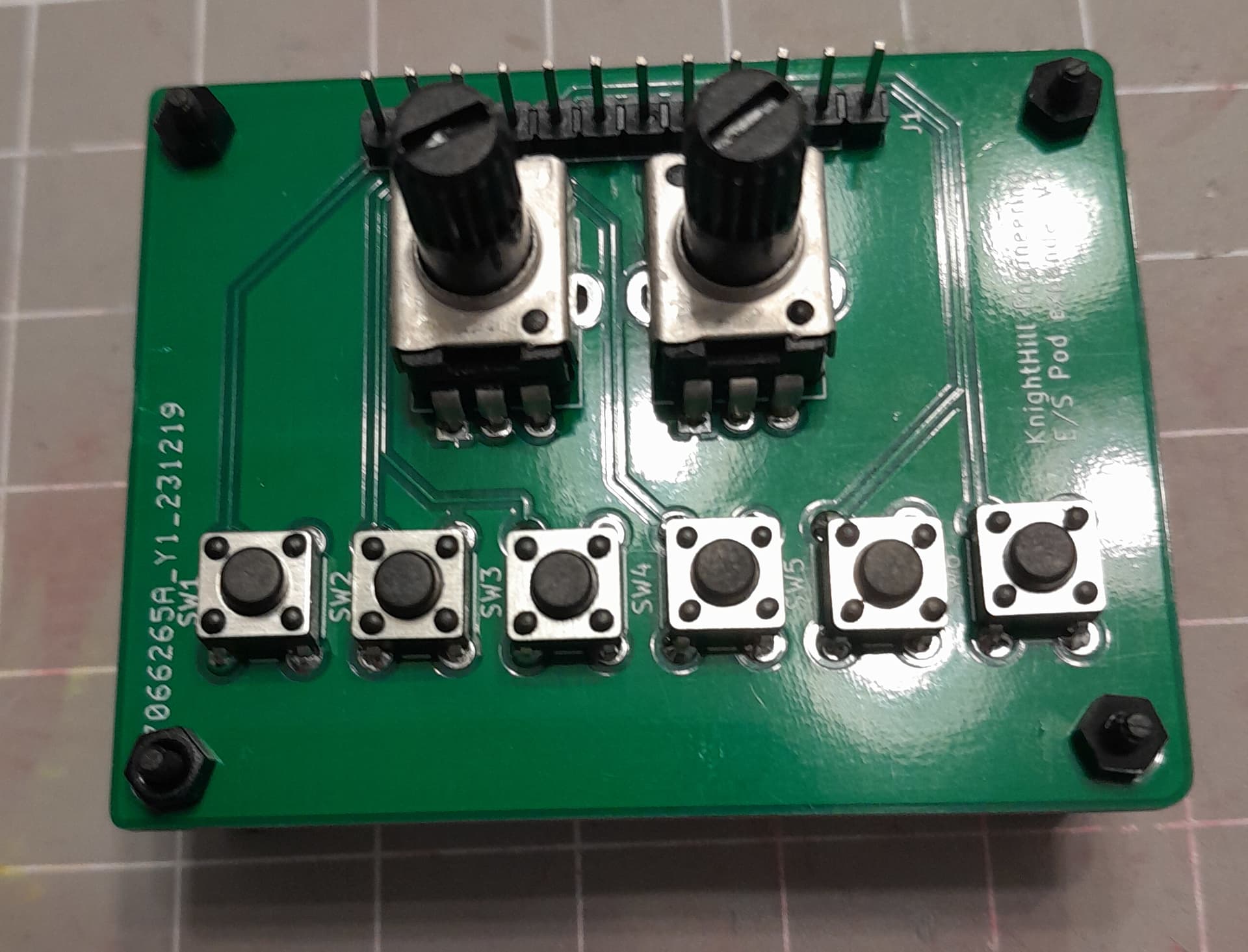
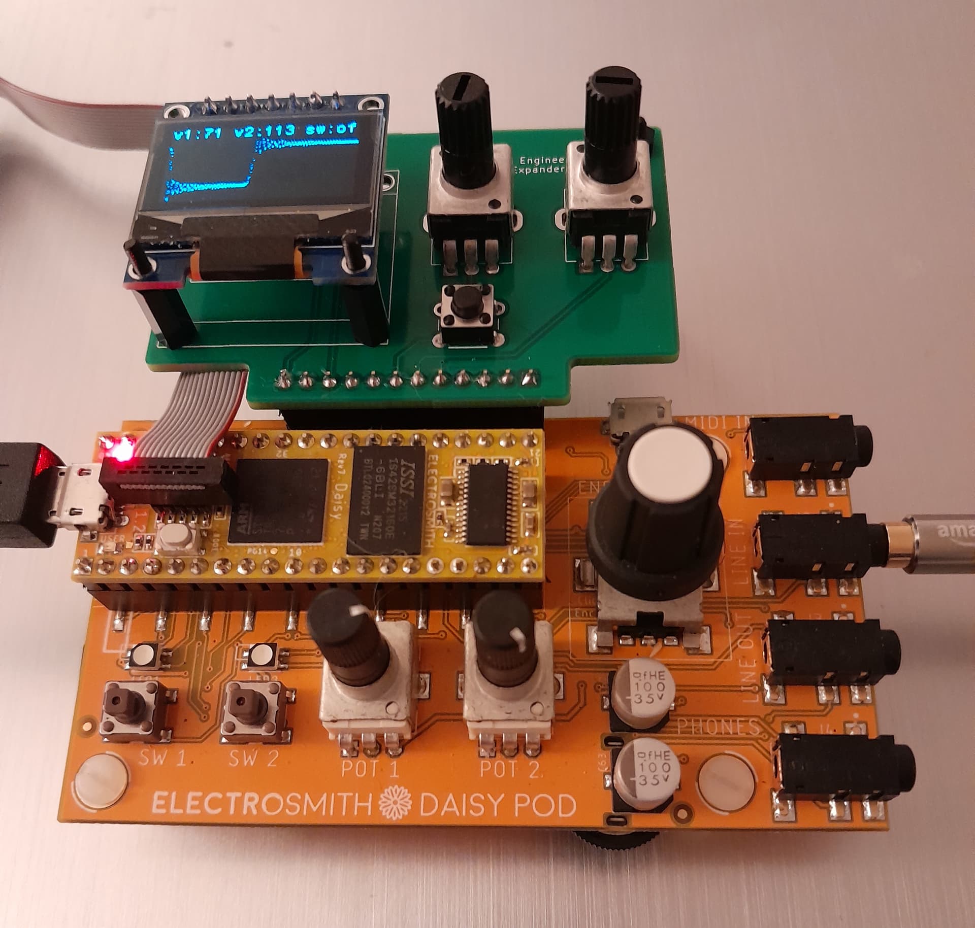
Just wanted to share my very first hardware project and my first fabricated PCB.
There are some minor issues like pot orientation, but overall it turned out pretty nice (for a beginner).
5 Likes
This awesome! And thank you so much for sharing.
I really like this idea of a “Pod-expander”. I can imagine there being various expanders for different components and swapping them around.
1 Like
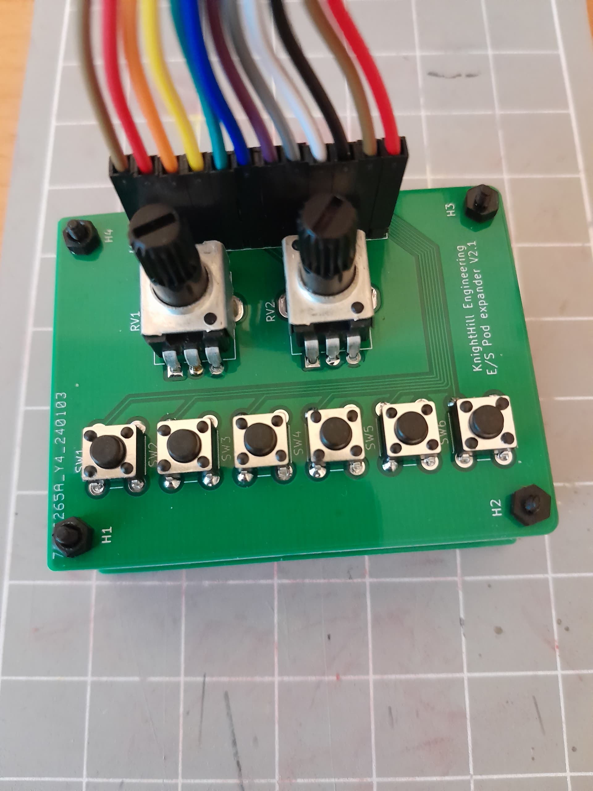
Version 2.1 is here with header/pot orientation fixes. Plans for the next version include 8 pots and 8 buttons.
3 Likes
Wow! Nice display. Kudos @KnightHill !
I would change that to an expander board with a generous helping of pads available for mounting encoders, switches, an oled or two, a joystick, etc.
An individual could choose to populate a given part or not depending on their needs. And you might be able to arrange some of the pads so it could have a choice of parts to keep the board frpm getting too ridiculous in terms of size - you could have eight encoder and eight switches or 16 encoders, etc. - including things that could be mounted instead of a display. That way you could get some different uses out of a single board.
1 Like
This is awesome!!! ![]()
1 Like
I like the idea. However, what could be done is quite limited by the number of pins exposed by the Pod. I am reaching a point where it looks easier to design a Pod-like board with the configuration that I want instead of further pushing the Pod expander.
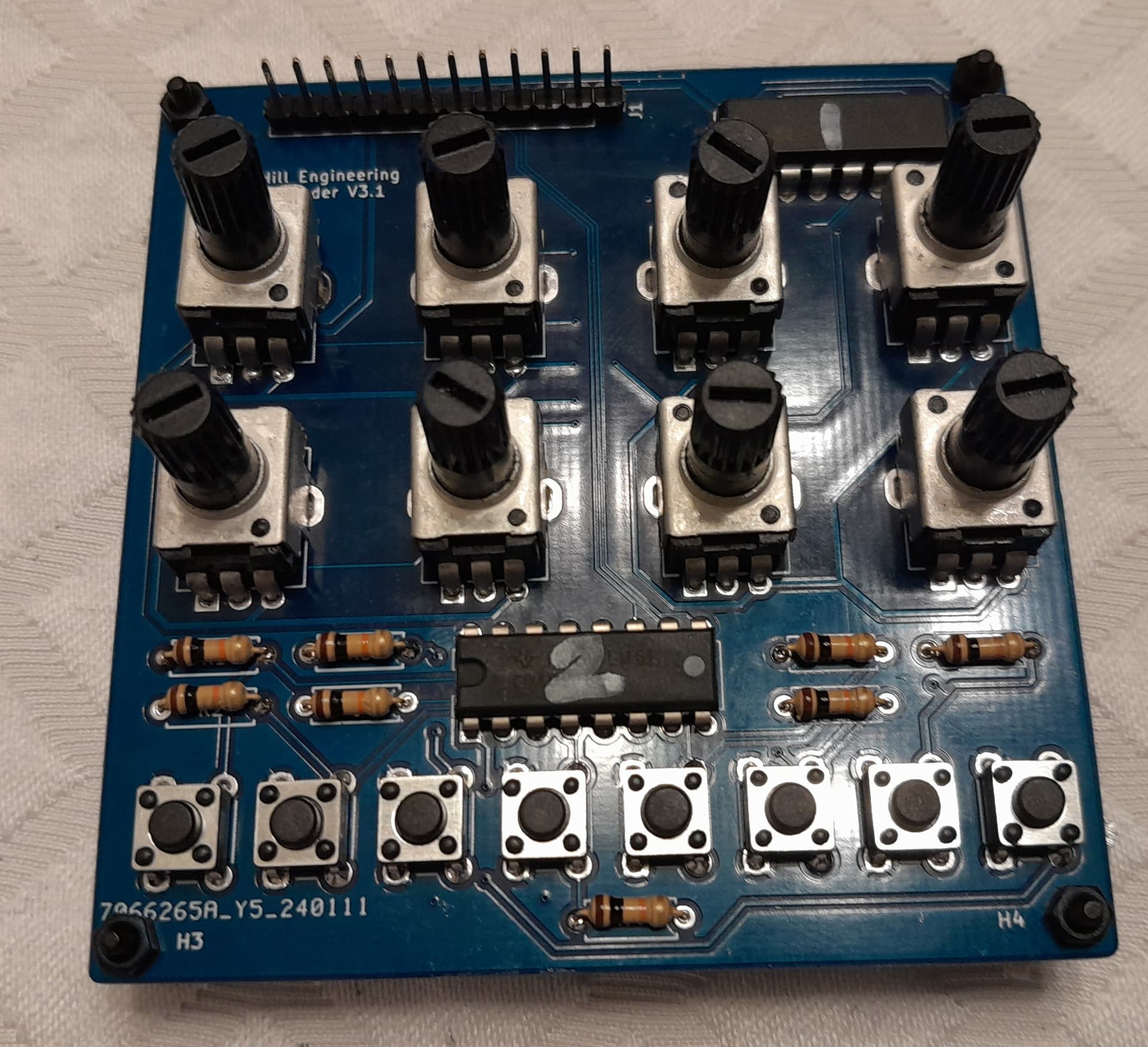
The next variant (below) is probably going to be the last before designing a Daisy board from scratch:
3 Likes
This all turned out amazingly!
It’s been awesome seeing the evolution of this project!
2 Likes
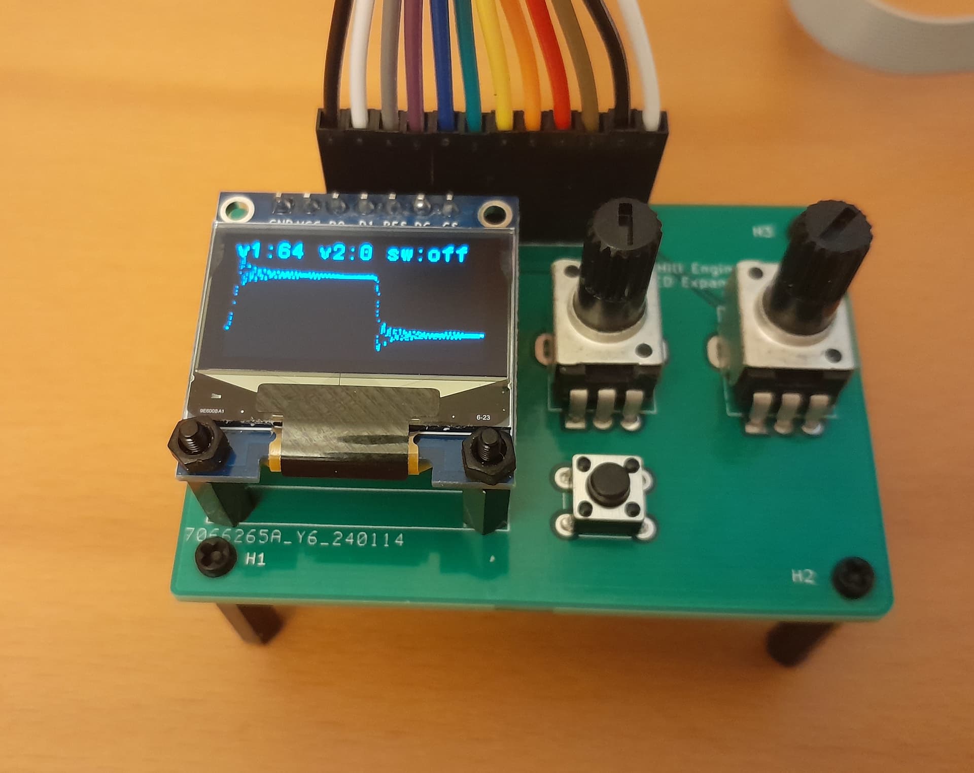
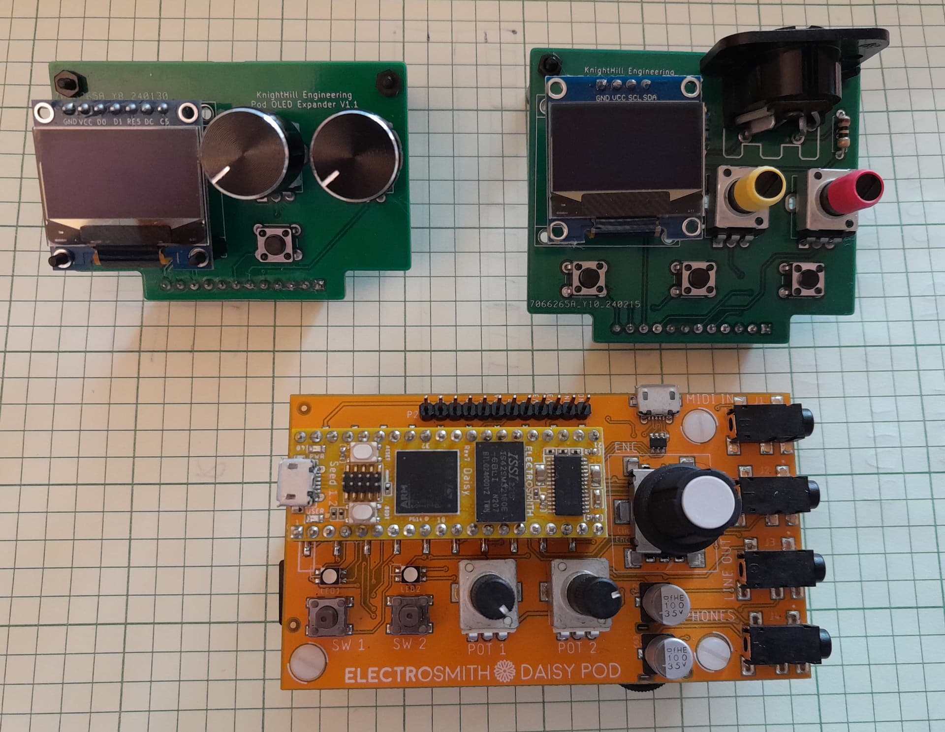
The latest iteration (I2C display + MIDI OUT) was a failure. A couple of observations:
- I2C displays are painfully slow compared to SPI. Definitely not something that can be used for real-time processes, like oscilloscopes
- It looks only pins D13/D14 and D29/D30 can be used for MIDI In/Out via USART. None of these is exposed by the Pod. My plan to use pin 9 failed miserably

SPI and I2C expanders side by side:
1 Like
Doesn’t the pod already have MIDI via a TRS cable?
Pod has MIDI IN only.
1 Like
This is a new github repo with the final version only. Firmware, KiCad 7 project and gerber files are included. Should work with KiCad 8. All parts are generic and should be available from Amazon/ebay.
2 Likes
Hi @KnightHill
I’m thinking of adding a MIDI out TRS to my Pod, but I don’t have any experience with components and programming (I’ve been using the Pod with Pure Data). Do you have any idea where I could start looking for information?
Thanks
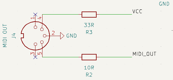
I would suggest starting with the hardware side first and then writing a PD json file that matches your hardware configuration. The MIDI out schematic is very simple, you just need to add 2 resistors and one MIDI DIN connector. Daisy exposes a couple of pins that can be used for MIDI Out. These are designated as USARTx Tx on the diagram.
The first step would be to find out if any of these are exposed via POD’s connector. From my notes, It looks only pins D13/D14 and D29/D30 can be used for MIDI In/Out via USART. However none of them are available in PODs connector.
Therefore, it seems the only option is not to use PODs external header, but to solder your MIDI out to Daisy’s pins directly. This can be done in the old version of the POD (the one that has female headers for all of Daisy’s pins).
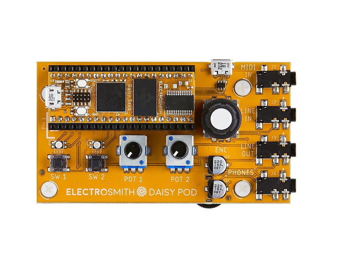
To avoid any confusion, this is how the old POD looks like:
Let me know if you have any additional questions.
1 Like
so I guess I have the newer version.
In this case where can I connect the resistance + Midi DIn?
I will be using a breadboard for this.
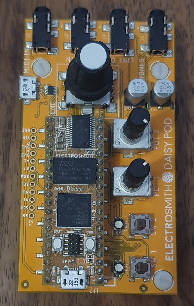
VCC is Daisy pin 38. MIDI OUT is connected to Daisy pin 14. GND is connected to pins 20 and 40.
1 Like
Thanks for the diagram.
I have connected the MIDI DIN as indicated.
How can I modify the json for PD/plugdata so that it can recognize the Midi output?
I don’t know much about PureData, but Mr. @dreamer can help you with the json config.
2 Likes
You don’t need to modify the json for the pod, it already enables midi i/o.
It only works with the standard rx/tx pins used in Daisy though, no custom pins (yet).