Hey everyone,
I’m still trying to figure out my MIDI input problem on the Daisy Seed. After realizing I needed a circuit before the USART1 Rx to make my MIDI dreams come true, I’ve been trying to duplicate the circuit from the Pod.
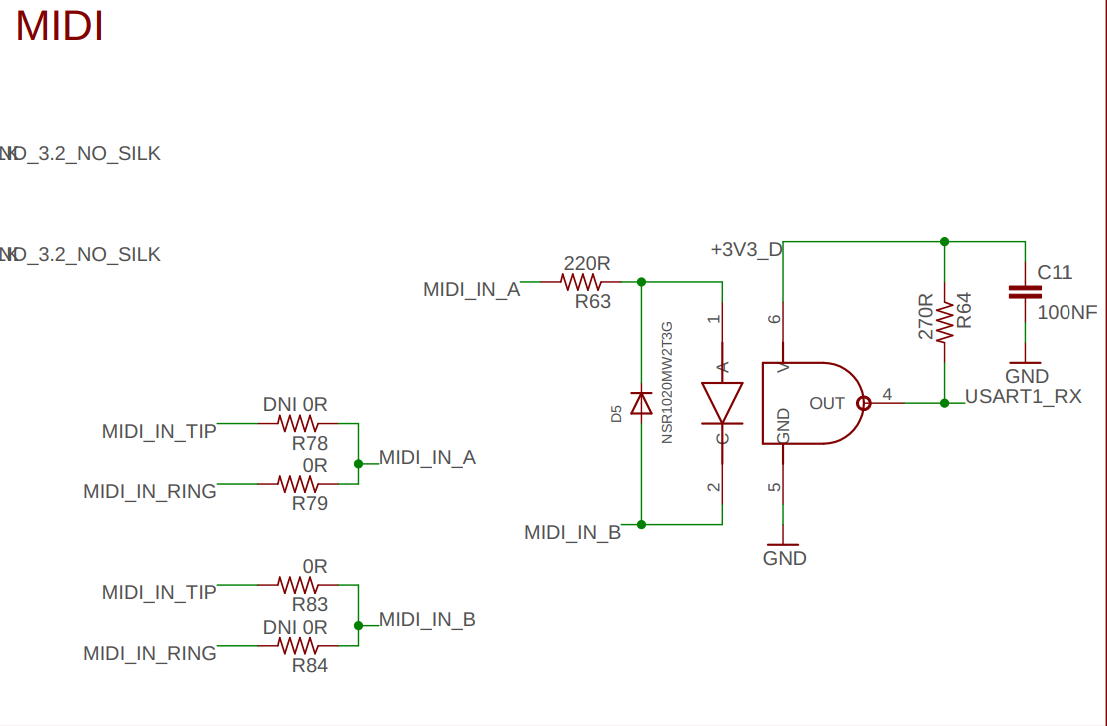
First image: from the Pod schematic. This one is a little confusing — I think it might be conflating “tip” and “ring” with MIDI in A and B. (I believe B isn’t actually used on the Pod.)
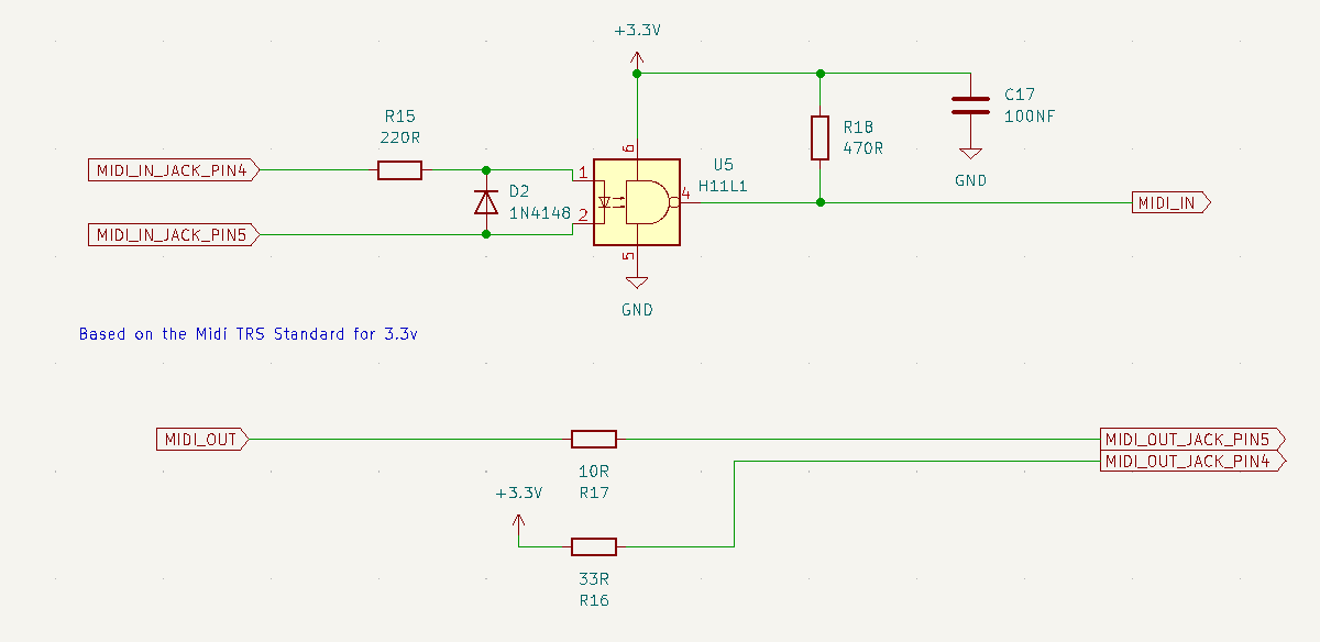
Second image: from the Electrosmith forum. This one makes more sense for the input side, but I still haven’t had any luck getting either schematic to work.
For parts:
Same optocoupler as the Pod: On Semi H11L1SR2.
Same values for the other components.
Since I’m on a through-hole breadboard, I swapped the Pod’s NSR1020MW2T3G surface-mount diode with a 1N5817 Schottky.
I also tried a 1N4148, as shown in the second schematic.
Same Daisy for both the Pod and breadboard circuits, both powered via USB.
I’ve combed through this simple circuit so many times that I feel like I must be missing something obvious that isn’t shown in the schematic.
Can anyone verify the schematics
, and maybe point out what I might be overlooking?
Thanks!
For input, those schematics are effectively identical, and correct. (Well, small difference of 270ohm and 470ohm resistors on the output side of optoisolator. Might not make a difference)
Some of your confusion probably comes from the Pod being able to use either Type A or Type B TRS MIDI cable. The selection is made by the choice of resistors on the input. As shipped, it is set up for Type A. DNI means Do Not Install, and 0R is a 0 ohm resistor, which is electrically just like a piece of wire.
And both MIDI_IN_A and MIDI_IN_B (on the optoisolator) must be connected to the ring and sleeve respectively, for use with a Type A cable.
Thanks for clarifying. I think I understand where my confusion was coming from…
Looking at the actual Pod schematic, it seems like it omits a connection for each MIDI type. For Type A, the ring goes through R220, while the tip doesn’t go anywhere since the 0R isn’t installed. That would mean the input of D5 should be “ring” at the cathode and “tip” at the anode, which lines up with the second schematic.
If that’s right, then it seems like things are set up correctly according to the second schematic. Is there possibly a connection outside of that path that I might be overlooking?
What are you plugging into this input, Type A or Type B? It could just be that tip and ring are crossed, as in plugging a Type B into a Type A. Flip the wires to test.
Thanks for the reply!
I’m using Type A, and I’ve tried swapping tip and ring with each change just in case, but the results are always the same- No MIDI signal.
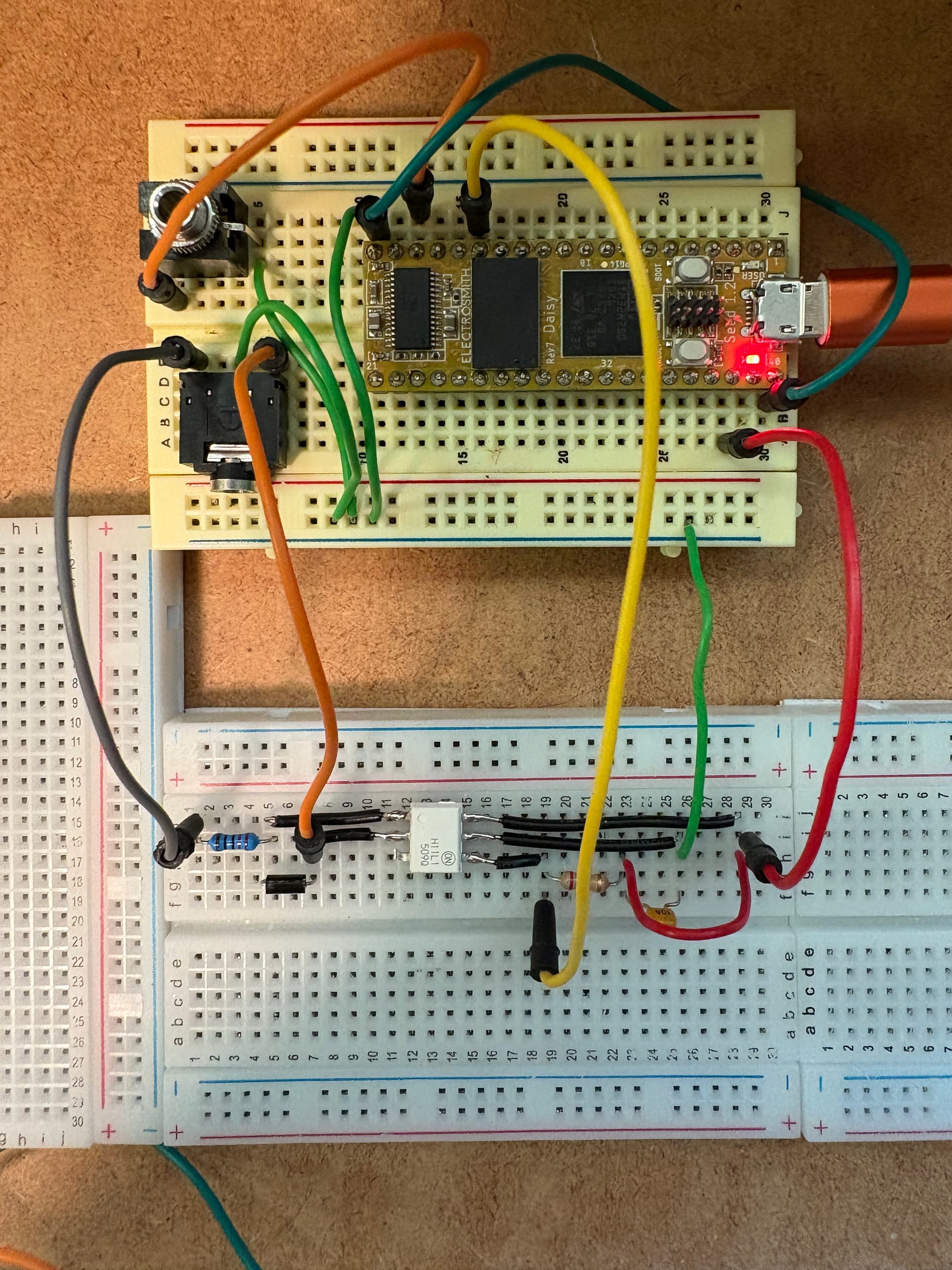
For context, here’s a photo of the current breadboarded circuit. This is actually my third attempt: I built it today with completely fresh parts and on a different breadboard, just to rule out bad components or connections.
I’m testing with a Critter & Guitari Organelle. The same Daisy Seed works perfectly with the Pod and the Organelle, and I can also get MIDI over USB on this breadboard setup. So it seems like the problem is specific to the MIDI input circuit.
On the breadboard:
-
Upper-left 3.5mm jack = single audio output
-
Lower-left 3.5mm jack = MIDI input
-
Ring is going to the 220R resistor
-
Tip is going to the anode of the diode
Does anything in that wiring look off to you, or is there something else
I might be overlooking?
I’m not good at tracing breadboard circuits in photos. A scope would be handy.
Are you certain you’re on the right pins for tip and ring?
I flip the tip and ring with every move I make. It can only be one or the other- The sleeve is ground in either case.
It may be time to crack open the Pod’s Eagle file and do some reverse-engineering. Because of the obvious errors in the official schematic, I have a sneaking suspicion that something else might be missing.
Thank you for the reply- I’ll report back!
What obvious error? That really is how you hook up MIDI input.
It looks like three wires on your TRS , should be two ( no ground connection.) I don’t recall if that would cause a problem, but it defeats the purpose of the optoisolator.
Got it. Thanks for pointing that out.
What I meant earlier is that on the Pod schematic, MIDI A and B or both missing a connection. With the DNI 0R, there’s only one path shown for each. Because MIDI requires two signal connections plus ground, it looks like the second signal for MIDI A is effectively the net labeled MIDI B on the schematic.
I see your point about the ground connection on my breadboard. I removed it to test, but unfortunately still no luck. And yes, I’ve tried flipping tip and ring again just to be sure.
I’m digging into the Eagle file now to double-check the full picture. I’ll report back once I’ve traced it through.
You are mistaken, the DNI resistors on the schematic are correct. The design allows (relatively) easy selection of either Type A or Type B midi cables. As shown, it is configured for Type A, nothing is missing. Move two resistors to the DNI locations for Type B. Old-style design would use two jumpers. For example with jumpers, see the Bluemchen schematic:
MIDI does not require two signals plus a ground. it requires a current loop. Again, that schematic is correct, stare at it until you get it.
With a scope, you could troubleshoot this in minutes. Maybe a bad connection, a bad cable, or a damaged optoisolator? Or maybe you’re not running a Daisy program set to OMNI, or the correct MIDI channel?