Hey there everyone,
I’m in the midst of trying to finish building a few FunBox pedals with Max Msp Gen~ and have been stuck on getting my three way SPDT toggle switches to function as expected. No matter what I try with both the .json file and Gen~ patch I can only get it to recognize two of the three positions. I’ve managed to get the potentiometers , LED’s and momentary/latching stomp switches to function no problem, but can’t seem to figure out why the toggle functions won’t work as desired.
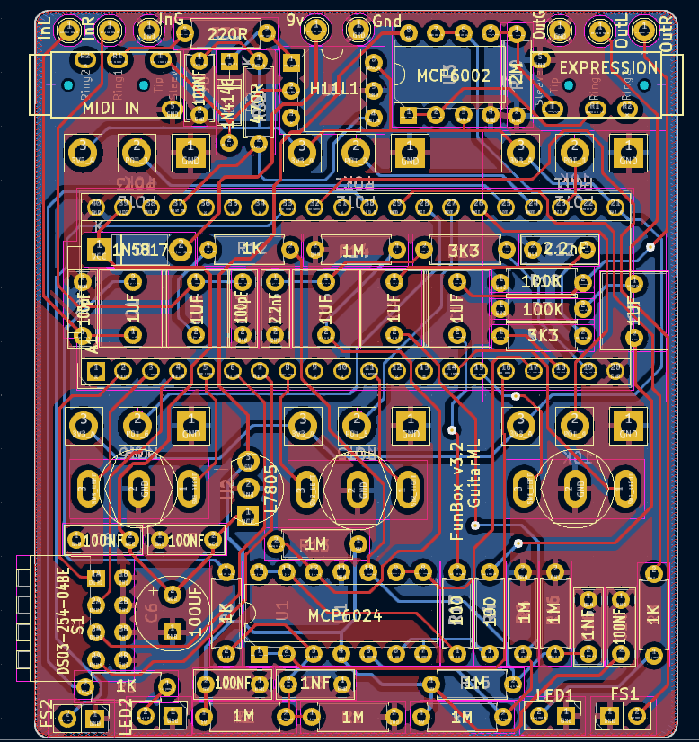
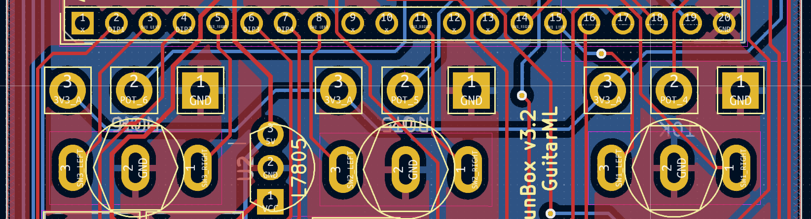
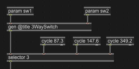
I have no idea if the problem lies my my .json file, the Gen~ patch or some combination of both at this point. I’ve attached the latest .json file I’ve been trying to use, screenshots of the Gen~ patch and the schematic page from KiCad for the particular PCB I’ve been using.
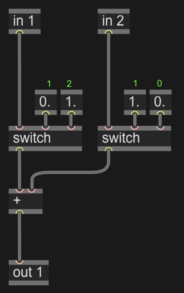
Based on my selector test these are the values I’m getting for some reason.
// Left: in1=1, in2=1
// Center: in1=1, in2=0
// Right: in1=1, in2=0
Any help with sorting this out would be greatly appreciated!
Hi there!
I still unfortunately haven’t been able to figure out the issue with the advice given in that thread or anywhere else. So I figured I should start a new thread here, that way I don’t needlessly clog up the previous thread with my issue which may have a completely different root cause issue.
I have no idea if I’m configuring the .json file incorrectly or not implementing it in Gen~ in the correct way. My recent multi-meter tests seem to indicate that the PCB board and soldering isn’t the issue, so I’m incredibly lost and bewildered at the moment.
Any help and guidance would be most certainly appreciated!
It’s so close… I seem to be getting the selector channels 1-2-2 with that update.
The left pin seems to be outputting 1-1-1 and the right pin seems to be 1-0-0, so I’m wondering if this issue has something to do with pull up and pull down resistors for the toggle switch pins? If so it seems to be a matter of implementing this in the .json file, but I can’t seem to get a difference when trying it. I’ve been trying to implement something along the lines of this.
This is all very confusing to me at the moment, especially when a multi meter test on the soldered PCB board indicates that things are functioning as expected? I’m still completely lost as to why this is happening and how to remedy such an issue.
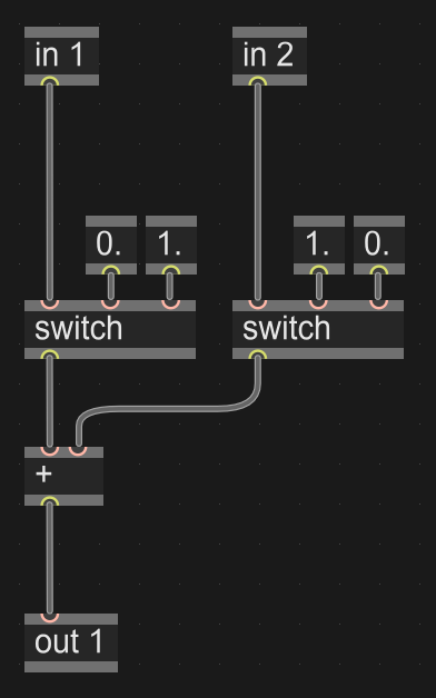
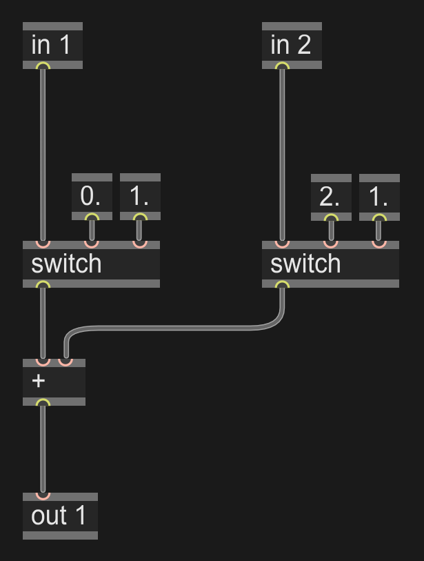
So after two weeks of experimenting I finally got a .json file to work with the FunBox’s three way toggle switch system. Turns out I just had the pins offset by one on the .json file.
Here it is in-case anyone else runs into the same issue I did, along with a screenshot of the gen~ patch that worked for combining the two pins.