Led and Switch3 Components not working / throwing errors on Patch_SM

hello,

running most recent dev branch of Oopsy, installed all well.

I cannot get my LEDs to respond at all. Here is my JSON file:

{
  "name": "estuary",
  "som": "patch_sm",
  "defines": {},
  "audio": {
    "channels": 2
  },
  "components": {
    "cv_1": {
      "component": "AnalogControlBipolar",
      "pin": "C5",
      "is_default": true
    },
    "cv_2": {
      "component": "AnalogControlBipolar",
      "pin": "C4",
      "is_default": true
    },
    "cv_3": {
      "component": "AnalogControlBipolar",
      "pin": "C3",
      "is_default": true
    },
    "cv_4": {
      "component": "AnalogControlBipolar",
      "pin": "C2",
      "is_default": true
    },
    "cv_5": {
      "component": "AnalogControl",
      "pin": "C6",
      "is_default": true
    },
    "cv_6": {
      "component": "AnalogControl",
      "pin": "C7",
      "is_default": true
    },
    "cv_7": {
      "component": "AnalogControl",
      "pin": "C8",
      "is_default": true
    },
    "cv_8": {
      "component": "AnalogControl",
      "pin": "C9",
      "is_default": true
    },
    "ADC_9": {
      "component": "AnalogControl",
      "pin": "A2",
      "is_default": true
    },
    "ADC_10": {
      "component": "AnalogControl",
      "pin": "A3",
      "is_default": true
    },
    "ADC_11": {
      "component": "AnalogControl",
      "pin": "D9",
      "is_default": true
    },
    "ADC_12": {
      "component": "AnalogControl",
      "pin": "D8",
      "is_default": true
    },
    "gate_out_1": {
      "component": "GateOut",
      "pin": "B5",
      "display": "",
      "is_default": true
    },
    "gate_out_2": {
      "component": "GateOut",
      "pin": "B6",
      "display": "",
      "is_default": true
    },
    "cvout": {
      "component": "CVOuts",
      "is_default": true
    },
    "gate_in_1": {
      "component": "GateIn",
      "pin": "B10",
      "is_default": true
    },
    "gate_in_2": {
      "component": "GateIn",
      "pin": "B9",
      "is_default": true
    },
    "led1": {
      "component": "Led",
      "pin": "D2"
    },
    "led2": {
      "component": "Led",
      "pin": "D3"
    },
    "led3": {
      "component": "Led",
      "pin": "D4"
    },
    "led4": {
      "component": "Led",
      "pin": "D5"
    },
    "led5": {
      "component": "Led",
      "pin": "D7"
    },
    "led6": {
      "component": "Led",
      "pin": "D6"
    },
    "led7": {
      "component": "Led",
      "pin": "D1"
    },
    "led8": {
      "component": "Led",
      "pin": "D10"
    }
  },
  "aliases": {
    "gate": "gate_in_1",
    "gate1": "gate_in_1",
    "gate2": "gate_in_2",
    "gateout": "gate_out_1",
    "gateout1": "gate_out_1",
    "gateout2": "gate_out_2",
    "cvout": "cvout1",
    "cv_out_1": "cvout1",
    "cv_out_2": "cvout2",
    "knob": "cv_5",
    "knob1": "cv_5",
    "knob2": "cv_6",
    "knob3": "cv_7",
    "knob4": "cv_8",
    "knob5": "ADC_9",
    "knob6": "ADC_10",
    "knob7": "ADC_11",
    "knob8": "ADC_12",
    "cv1": "cv_1",
    "cv2": "cv_2",
    "cv3": "cv_3",
    "cv4": "cv_4",
    "cvin1": "cv_1",
    "cvin2": "cv_2",
    "cvin3": "cv_3",
    "cvin4": "cv_4"
  }
}
Hey @garrettlaroyjohnson!

Could you flash the Patch.Init() example patch with the corresponding board selected and then test if the gate out is working with your LED?

Please make sure that your SM is powered with ±12V power for it to work fully by the way.

Hi @Takumi_Ogata :slight_smile:

The GateOuts work great for triggering etc. in CV contexts – I will try to output to an LED in a second here.

When the module is turned on in the Eurorack case (powered by 12v) in bootloader mode, 6/8 of the LEDs do turn on.

Alright,

Since all my LEDs are soldered into place, I used an external LED w resistor on a breadboard, powered and blinked successfully with Patch Init JSON and oopsy patch_init template. I patched a cable out from the gate_out_1.

Not sure if this was exactly what the suggestion was? let me know, thanks @Takumi_Ogata

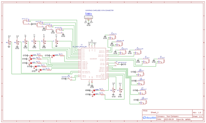
I’m wondering exactly how the LEDs are wired.

hello @tele_player thanks for your time.

here’s the schematic:

LEDs look appropriately wired - did you get a board made from that schematic?

Not relevant to LED issues, but just as a comment: assuming those on-on switches are really on-on, they waste two pins.

hi Tele_player, I did get a board made from them.

I am using on-off-on switches. The switches are mislabeled in the schematic – my mistake. I followed the diagram in the datasheet, so here’s to hoping there’s no unexpected errors. Is that what you’re referring to?

thanks for reviewing the LED issue. I’m somewhat relieved it seems to be a software issue.

Yes, that wiring looks OK for on-off-on.

If it was me, I’d write C++ (or Arduino) to verify the hardware, maybe check the LEDs with a multimeter , too.