Learn Arduino Guitar Effects with me. Project 1 - Audio Pass Through

Hi everyone.
I’m going to start off by saying that I’m a VERY amateur programmer and brand new into DSP. After building a bunch of analog guitar effects over the years, I caught wind of the Daisy Seed and thought that it would be fun to tinker around with. However, there are very few resources on learning how to program it. The mods on this forum seem to be active and very helpful, but I believe they’re putting most of their resources into improving the Daisy.
I’m still learning C++ and I have some Arduino experience, so I figured I’d start out with that. If you have limited programming experience (like myself) and opened up an example, you’ll see that very few of them have comments and can be confusing. I may not be the best or most capable, but I believe that contributing something, however basic, is better than not contributing at all. To build a better and lasting community, we need to help out the newbies.

My goal is to help newer people to read and understand the code, and also to be able to pick apart and dissect examples to create their own stuff.

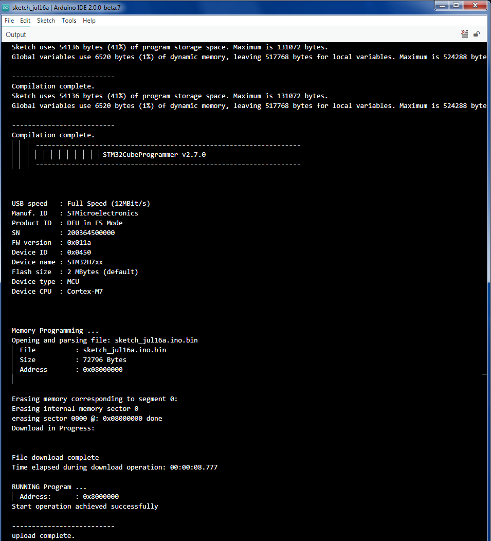
I’m assuming that you were able to configure Arduino and are able to upload a program to the Seed. I know I had several frustrating hours to get it to work only to find a post in the forum about not installing an updated version of stm32duino.

Getting Started:
When I first hooked up my Daisy Seed to a breadboard and some 1/4" guitar jacks, it was very noisy, low volume, and muddy. This is because the guitar output signal is very low compared to what the Seed can handle. We can fix these problems by making an input and output buffer. The buffer will amplify the signal a bit and block out the noise. There is another post on this forum about buffers, but to make it easy, I just picked up the Terrarium PCB from pedalpcb.com. It works great (however, I don’t have any pots or switches hooked up to it yet!). If you’re brand new to programming, I would highly recommend watching some YouTube videos on basic Arduino or C programming. I’m currently watching this 10 hour video on C++. The young dude is a fantastic intructor and would highly recommend watching it. https://youtu.be/_bYFu9mBnr4

The Code:
Many of the examples use left and right channels. Since we’re here just making single channel guitar effects, we can ignore a lot of the example code. For the first few examples, I’m also going to leave out any potentiometers and switches. We’ll just hard code everything for simplicity. I wrote a very simple input to output straight-through program just to get a ‘boiler plate’ program working. Copy this code into Arduino and upload it to your Seed.

#include <DaisyDuino.h>

DaisyHardware hw;

static void AudioCallback(float *in, float *out, size_t size)
{
  for(size_t i = 0; i < size; i++)
  {
    out[i] = in[i];
  }
}


void setup() {

  hw = DAISY.init(DAISY_PETAL, AUDIO_SR_48K);

  DAISY.begin(AudioCallback);

}

void loop() {
  // put your main code here, to run repeatedly:

}

Great! You should hear your guitar going through the Seed and out into your amp. Now what’s going on? Let’s take it step by step.

#include <DaisyDuino.h>

This statement allows Arduino to access the DaisyDuino header and libraries. The header contains all the necessary stuff to interface and compile the program from Arduino to our Seed.

DaisyHardware hw;

Here, we’re creating an object, hw, of the DaisyHardware Class which is built into the DaisyDuino library. It makes it easier for us to access the class without cumbersome code. We’re going to skip the next section for now and jump to the void setup

void setup() {

  hw = DAISY.init(DAISY_PETAL, AUDIO_SR_48K);

  DAISY.begin(AudioCallback);

}

void loop() {
  // put your main code here, to run repeatedly:

}

So what’s going on here? When an Arduino program runs, the very first thing it does is run through the code in the ‘void setup’ function. It only runs this code once. The next line in this function ‘hw = DAISY.init(DAISY_PETAL, AUDIO_SR_48K);’ is how we’re going to initialize our Seed. It’s going to assign all the input/output pins to be that of a Daisy Pedal (which I don’t have, but the Terrarium is indentical for our purposes) and have a sample rate of 48k.
After that, we need to start processing audio with ‘DAISY.begin(AudioCallback);’ This is going to call the AudioCallback function and run on effectively a loop. Because of this, we don’t need anything in the void loop(){} function, but Arduino requires that loop function to compile.

static void AudioCallback(float *in, float *out, size_t size)
{
  for(size_t i = 0; i < size; i++)
  {
    out[i] = in[i];
  }
}

To be completely honest, this is magic to me. I’ve looked around and there are virtually no references on what really goes on inside the DaisyDuino. I’m sure if you dig deep enough you can find a better explanation, but for now, realize that you need this code to make any program to work.
As far as I can tell, when you call the AudioCallback function using DAISY.begin, it defines in and out as floats. The * points to a location, which I assume is defined in the header as the input and output pins. The program runs this function whenever it has audio to process. I haven’t figured out what the ‘size_t size’ does yet, but you need it for the subsequent ‘for’ loop. Inside that ‘for’ loop is what actually processes our code. In this instance, we’re just making the output to be equal to the input by doing ‘out[i] = in[i];’

So we walked through our first, simple program, but I’m not too happy with it. Fidelity is pretty good, latency is not noticable at all, but I found the output volume a bit too low. Let’s fix that with a quick adjustment.

out[i] = in[i] * 2;

There we go. The volume on the amp is about the same if I have my guitar plugged in through the Seed or not. Next, let’s make a simple distortion effect!

5 Likes

Hey man, I’m still waiting on my Petal, but just to let you know, got the notification for this thread today in my e-mail and very stoked that you started something like this. Once I get my Petal I’ll join with what you’re doing here, I started to explore Max 8 and bought myself the crossover version of Max from M4L, but I’ll be glad to switch topics back and forth to get into this Arduino coding with you. I’m also interested in making guitar pedal effects with this thing so I’ll stay tuned to what you post on the forum. Super noob myself, so very happy to see you took the initiative to start a thread like this.

1 Like

Sorry I’m a bit late with this follow up. I just copied and pasted the text into my Arduino IDE, uploaded the file to my board and it worked like a charm. Audio is heard from my Fender Squier Strat, into the Daisy Petal, and out through my small BOSS Katana amp.

Yes, I did have to format my old Daisy with ZADIG (link to the Github page) on Windows. The new one that I got was already formatted.

This Github page (link) has all the steps for Windows, I followed them and believe my environment has been set up correctly.

For those of you interested in the exact details, I’m running:

  1. A Windows 7 Ultimate SP1 (aka Service Pack 1) 64-bit OS.

  2. Arduino IDE
    Version: 2.0.0-beta.7
    Date: 2021-05-17T10:10:22.608Z (1 month ago)
    CLI Version: 0.18.3 alpha [d710b642]

  3. My Arduino settings for upload are:

In the “Boards Manager”, I have marked as “INSTALLED” the [DEPRECATED] Ver 1.9.0 of the STMicroelectronics library for Generic STM microcontrollers. (Important! As the newer version gave me issues, haven’t checked for a new version with a fix for this yet, this is a known issue)

In the “Library Manager”, the DaisyDuino by stephenhensley Version 1.3.0 is marked as “INSTALLED”.

Under the “Tools” drop-down menu, following these steps:

Tools → Board → [Deprecated] → I selected “Generic STM32H7 Series”

Port → I selected “COM1” in my case.

Board Part Number → I selected “Daisy”

Upload Method → I selected “STM32CubeProgrammer (DFU)”

USB support (if available) → I selected “CDC (generic ‘Serial’ supercede U(S)ART)”

U(S)ART support → I selected “Enabled (generic ‘Serial’)”

USB speed (if available) → I selected “Low/Full Speed”

  1. I held the “Boot” button and clicked the “Reset” button to put the Daisy Seed into upload mode.

  2. Other settings left by default. I hit the upload button and got this screen after 10 seconds.

I was using USB 3.0 to upload and the USB cable was a data cable, not just a power cable. This is a very common mistake since not all USB cables are made the same. I think a “micro USB” cable that came with your smartphone (I think the USB C type cable is becoming more common now though) should be able to do this, but don’t take my word for it.

Hope this helps someone.

1 Like

Hello! First off, thank you for your willingness to help the newbies here, really glad to see it.

Secondly,

What part of the code, would need to be changed to get this working with Eurorack levels as well as stereo outs? I currently have built the Audio buffers from the patch schematic but can’t seem to get the passthrough to work. Any help would be appreciated! Thanks!

Are you trying to upload code to a Daisy Patch? Sorry I can’t be more useful with this at the moment, I would be interested in learning how to do this too.

What part of the code, would need to be changed to get this working with Eurorack levels as well as stereo outs?

So I think the problem is, is the initialization of the Daisy is different for the patch vs the petal. The patch supports 4 inputs and outputs and the petal supports 2, among other controls. They MAY use different input/output pins that are defined somewhere. To do that, we would need to change our init statement.

hw = DAISY.init(DAISY_PATCH, AUDIO_SR_48K);

I may be completely wrong, and I’m certainly not the best source of information for info or help on here. Let me know if it works. Maybe someone else can chime in and fill in the blanks.

I don’t know anything about Eurorack, but I would guess just have an out[i] = int[i] * (whatever gain integer make it work). It’s all dependent on your buffer circuit and guitar.

For stereo outs (provided your circuit is correct to the patch), you can have 4 inputs and 4 outputs. So all we need to do is basically vectorize our ins and outs.
To be honest, I don’t know why or how this works, but this is what it looks like in the example code.

out[0][i] = in[0][i];
out[1][i] = int[1][i];
1 Like

Nice post, and surely welcome. I’m also trying to make a multi-effect pedal with Daisy Seed. I’ve been using the following set:

DaisyHardware hw;

void setup {

hw = DAISY.init(DAISY_SEED, AUDIO_SR_48K);
num_channels = hw.num_channels;
sample_rate = DAISY.get_samplerate(); // selected sample rate
DAISY.SetAudioBlockSize(1); // Just one sample per audio callback
DAISY.begin(MyCallback);

}

void MyCallback(float **in, float **out, size_t tsize)
{

static float sample;
sample = in[0][0];
if (effect_1.state == ON) sample = effect_1.Process(sample);
if (effect_2.state == ON) sample = effect_2.Process(sample);

out[0][0] = sample;
out[1][0] = sample;
}

Sound processing is performed once per sample, by setting SetAudioBlockSize(1). This avoid latency. Moreover the time spent to process 48 samples is 48 times longer than the time spent to process a single one.
The second input channel (in[1][0]) can be used to sample the audio level. Just pass the audio signal to a rectifier and a filter before connecting it to ADC input. The audio level is useful to a compressor, or a sustain, or a auto-wah among others.
The effect.state acts as the effect switch, selecting on or off (bypass).

This can generate a discontinuity when you toggle effect. Result would sound like a click. It would be propagated to next effect and that’s especially bad if it ends up in a feedback loop of delay or reverb. To avoid this you can crossfade between dry and wet signal at transients instead of switching to 100% instantly. Or the other way around for switching audio off. Doing it for something like 32-64 samples should be good enough.

EDIT: And for delay based effects you would have to fade in dry signal sent to effect

If you use it for non-trivial code, it would end up taking more CPU time at the due to decreased cache performance and more function calls compared to block based processing. The latency from those 47 samples at 48kHz is the same as moving 33.5 cm closer to your speaker, so we’re not talking any major decrease here. Whatever block size you use, it’s a trade-off in something.

This can generate a discontinuity when you toggle effect…

That’s true. I didn’t realize that, but the tests I’ve been carrying out didn’t show any click or noise. Anyway you’re right and I have to take care of it.

If you use it for non-trivial code, it would end up taking more CPU time at the due to decreased cache performance and more function calls compared to block based processing…

Indeed. I usually think that a good digital guitar effect has to be short, fast and with low latency. However, my knowledge of using and handling cache isn’t enough yet to say how far of fast we can go. Could a multi-core processor be an effective way to recover the lost cache performance? For instance, you can process effect_1, 2 and 3 in processor A, then deliver the output to processor B to process effect_4 and so on. I already used this strategy with ESP32 and it worked fine.

The Daisy CPU is very fast, you can do many simultaneous effects without needing multiple cores, and you can get very acceptable latency performance without incurring the high overhead of tiny buffers.

It obviously depends on audio volume that is processed when you switch. So if you don’t play anything and there’s no delays in current effect, you likely won’t notice anything because signal level is close to 0. But either way, it has to be solved to be able to switch any effects at any time.

I didn’t mean that it’s a huge problem, just that there’s some overhead from not using block based processing. It’s a valid choice for some cases and you still get ~10k CPU cycles per sample either way, but it doesn’t always has to be the best choice.

Well this way you spend N CPU cycles processing effects 1-3, then M CPU cyles for effects 4+. If you do it on 1 core, you would also spend the same N + M cycles. So what are you expecting to improve this way? You can improve performance by utilizing more cores if you have some effects running in parallel and mixed later, but not for such sequential processing.

Multi-core microcontrollers from ST Microelectronics only offer the same core as used on Daisy + a smaller one (can run about 1/3 of computations), so no major improvements are to be expected. True SMP cores are available on their bigger ARM processors, but that’s a very different story.

So what are you expecting to improve this way? You can improve performance by utilizing more cores if you have some effects running in parallel and mixed later, but not for such sequential processing.

Well, in fact I should say “to increase the number of effects that I could include in chain” instead of “improving performance”. ESP32 has two cores, but performance wasn’t enough to fit something like 10 effects on chain (I already developed 18 effects myself) in a single core. So I divided chain in two, with half of effects in each core. The drawback was that I only could change the effect position in chain by uploading a new code. Anyway, I didn’t go further with this project because the ESP32’s ADC wasn’t appropriate for audio processing (much noise and some hangs). However I achieved 44.1 kHz audio processing with it. So I started to work with Daisy, but the final code exceeded the 128kB of Daisy’s flash. Now I’m waiting the new upgrade in Daisy library, that shall extend the QSPI capability to store code. On the other hand, I’m also working with DevEBOX, which is a STM32H743 based board, with 1 MB flash, but I’m facing difficulties to make the program work either in Arduino IDE or within STM32CubeIDE.

Yup, quite a common issue. Eventually there would be a solution for running larger patches from QSPI and a bootloader, but for now it frequently becomes a problem. I would estimate that you need 60-90kb of code for hardware stuff from libDaisy and 30-40kb for a typical patch with a relatively small amount of effects. It’s easy to exceed this and run out of flash and you can’t rely on providing LUTs for optimization unless you generate them in memory from your patch. Have you tried building it with -Os to see if helps enough to fit on flash?

For comparison, when running OWL on Daisy Patch firmware code is separate from patches and patch size limit 80kb - but that’s entirely for you code and I’ve never ran into code limit size. It’s also possible to support patches up to 512kb running from another section of SRAM. And patches are stored on QSPI, so you have 7.5Mb for storing them. And there are LUTs for faster computing of exp/pow/FFT provided from firmware, more can be stored and read from QSPI storage. Unfortunately I’ve only ported it to Daisy Patch, don’t have other hardware.

In reply to @antisvin: Sorry for the late reply. I’m very busy these days. Yes, I’ve tried -Os (see Link optimization), but unfortunately the USB CDC serial becomes unavailable under -Os option. So I couldn’t communicate with DS. No patch to correct this behavior with DaisyArduino was released up to now. QSPI may solve the problem, and according to ElectroSmith, the Daisylibrary will support code storage on QSPI in the upcoming version. I’m just waiting for that.

Well that upcoming version already came out. And bootloader usage was explained here: Creating a Bootloader via the Uart - #18 by shensley