Hi, as a simple trial I though I’d connect a LED and resistor to the Seed and try to make it flash on and off. But I’m experiencing difficulties finding out how to use the GPIO ports. I take it I have to know a port address, set it to output and then toggle its value. Can anyone refer me to some code example that directly uses a GPIO as output?
1 Like
You should start at Daisy GPIO header and this examples for Daisy Seed
Thx. When I look at the code I find definitions for GPIO pins, like this:
#define GPIO_0
{
DSY_GPIOA, 8
}
#define GPIO_1
{
DSY_GPIOB, 12
}
When I look at schematics of the Seed (rev 4), I do not find a label called GPIOA, or a correspondence between the first GPIO-port and the number 8. Can you explain how this mapping works? E.g. is 8 meant to be the physical pin number of the Seed?
Or conversely,
if I want to address pin 27 of the Daisy, which GPIO-port will that be?
This is mapping between Daisy seed pins and MCU pins. MCU pin include port number (i.e. GPIOA) and pin number (8). This mapping can also be found here - https://github.com/electro-smith/libDaisy/blob/master/src/daisy_seed.cpp#L12-L48
If you only want to use them for GPIO and are using libDasy, it’s sufficient to know Daisy pin name, because Daisy pin numbers and not MCU pins are used in libDaisy code for addressing GPIO pins. Pin 27 would be connected to GPIOG9 on MCU - if you actually mean GPIO pin number (because Daisy has also non-GPIO pins for power supply and audio).
// GPIO 1-8
//{DSY_GPIOA, 8}, // removed on Rev4
{DSY_GPIOB, 12},
{DSY_GPIOC, 11},
{DSY_GPIOC, 10},
{DSY_GPIOC, 9},
{DSY_GPIOC, 8},
{DSY_GPIOD, 2},
{DSY_GPIOC, 12},
// GPIO 9-16
{DSY_GPIOG, 10},
{DSY_GPIOG, 11},
{DSY_GPIOB, 4},
{DSY_GPIOB, 5},
{DSY_GPIOB, 8},
{DSY_GPIOB, 9},
{DSY_GPIOB, 6},
{DSY_GPIOB, 7},
// GPIO 17-24
{DSY_GPIOC, 0},
{DSY_GPIOA, 3},
{DSY_GPIOB, 1},
{DSY_GPIOA, 7},
{DSY_GPIOA, 6},
{DSY_GPIOC, 1},
{DSY_GPIOC, 4},
{DSY_GPIOA, 5},
// GPIO 17-24
{DSY_GPIOA, 4},
{DSY_GPIOA, 1},
{DSY_GPIOA, 0},
{DSY_GPIOD, 11},
{DSY_GPIOG, 9},
{DSY_GPIOA, 2},
{DSY_GPIOB, 14},
{DSY_GPIOB, 15}
Starting from the table in the code you refer to, how do I find pin 27 of the daisy seed to correspond to GPIOG 9?
I think there is a mistake in the comments of the file, but even so the 27th entry is GPIOA, 0
By sheer luck I got an led to blink at pin 31, using GPIOA1, that also puzzles me, given this table.
Judging by pinout, you’re counting all pins. So that number 31 is probably 32 on pinout (they start from 1 in this case), which corresponds to GPIO pin 25 in libDaisy.
here’s how it’s done in some of the other Daisy examples:
Define Pin:
#define PIN_GATE_OUT 17 // this is the daisy pin number
dsy_gpio gate_output;
Init Pin:
gate_output.pin  = seed.GetPin(PIN_GATE_OUT);
gate_output.mode = DSY_GPIO_MODE_OUTPUT_PP;
gate_output.pull = DSY_GPIO_NOPULL;
dsy_gpio_init(&gate_output);
Set Pin:
dsy_gpio_write(&gate_output, true);  // set high
dsy_gpio_write(&gate_output, false); // set low
Hope this helps!
4 Likes
Thx, this helped me a bit further, but I’m not there yet I’m afraid.
I had a look at the schematic of the pod and saw that it connects a few LEDs to pins 25, 26, 27 and to pins 24, 31 and 30 (and via a resistor to pin 21, i.e. 3v3). I assumed all of those are GPIOs that can be set to output mode. So following your code example I entered those for my Led pins. Alas, only 1 led flashes when I run the following code:
dsy_gpio ledR_1_pin, ledG_1_pin, ledB_1_pin;
dsy_gpio ledR_2_pin, ledG_2_pin, ledB_2_pin;

// R 1 on pin 27
ledR_1_pin.pin = seed.GetPin(27);
ledR_1_pin.mode = DSY_GPIO_MODE_OUTPUT_PP;
ledR_1_pin.pull = DSY_GPIO_NOPULL;
dsy_gpio_init(&ledR_1_pin);
dsy_gpio_write(&ledR_1_pin, true);

// G 1 on pin 26
ledG_1_pin.pin = seed.GetPin(26);
ledG_1_pin.pull = DSY_GPIO_NOPULL;
ledG_1_pin.mode = DSY_GPIO_MODE_OUTPUT_PP;
dsy_gpio_init(&ledG_1_pin);
dsy_gpio_write(&ledG_1_pin, true);

// B 1 on pin 25
ledB_1_pin.pin = seed.GetPin(25);
ledB_1_pin.mode = DSY_GPIO_MODE_OUTPUT_PP;
ledB_1_pin.pull = DSY_GPIO_NOPULL;
dsy_gpio_init(&ledB_1_pin);
dsy_gpio_write(&ledB_1_pin, true);

// R 2 on pin 24
ledR_2_pin.pin = seed.GetPin(24);
ledR_2_pin.mode = DSY_GPIO_MODE_OUTPUT_PP;
ledR_2_pin.pull = DSY_GPIO_NOPULL;
dsy_gpio_init(&ledR_2_pin);
dsy_gpio_write(&ledR_2_pin, true);

// G 2 on pin 31
ledG_2_pin.pin = seed.GetPin(31);
ledG_2_pin.mode = DSY_GPIO_MODE_OUTPUT_PP;
ledG_2_pin.pull = DSY_GPIO_NOPULL;
dsy_gpio_init(&ledG_2_pin);
dsy_gpio_write(&ledG_2_pin, true);

// B 2 on pin 30
ledB_2_pin.pin = seed.GetPin(30);
ledB_2_pin.mode = DSY_GPIO_MODE_OUTPUT_PP;
ledB_2_pin.pull = DSY_GPIO_NOPULL;
dsy_gpio_init(&ledB_2_pin);
dsy_gpio_write(&ledB_2_pin, true);

   while(1) {
        dsy_gpio_write(&ledR_1_pin, true );
        dsy_gpio_write(&ledG_1_pin, true );
        dsy_gpio_write(&ledB_1_pin, true );
        //
        dsy_gpio_write(&ledR_2_pin, true );
        dsy_gpio_write(&ledG_2_pin, true );
        dsy_gpio_write(&ledB_2_pin, true );
        dsy_system_delay(d1);
        //
        dsy_gpio_write(&ledR_1_pin, false );
        dsy_gpio_write(&ledG_1_pin, false );
        dsy_gpio_write(&ledB_1_pin, false );
        //
        dsy_gpio_write(&ledR_2_pin, false );
        dsy_gpio_write(&ledG_2_pin, false );
        dsy_gpio_write(&ledB_2_pin, false );
        dsy_system_delay(d2);
 }
Only led G 2 flashes, which is connected to pin 31.
Does this mean that pins 24, 25, 26, 27 and 30 can not be used like this?
Any thoughts?
-
You’ve linked to schematics for Patch, not Pod
-
On Pod schematics R1 is GPIO21, G1 is GPIO20, B1 is GPIO 19.
-
Looks like you’re still confusing numbers for pins on Daisy and GPIO pin numbers that libDaisy uses, that’s why you count GPIO25 as pin 31
Sorry for using the wrong link, but I was actually looking at the Pod schematic.
What I find confusing is that when I use GPIO21, 20 and 19, see code below, (and 18, 25 and 24 for the other 3 leds) not all led are flashing?!
code snippet:
ledR_1_pin.pin = { DSY_GPIOB, 1 };
ledR_1_pin.pin = seed.GetPin(21);
ledR_1_pin.mode = DSY_GPIO_MODE_OUTPUT_PP;
ledR_1_pin.pull = DSY_GPIO_NOPULL;
dsy_gpio_init(&ledR_1_pin);
dsy_gpio_write(&ledR_1_pin, true);

// G 1
ledG_1_pin.pin = seed.GetPin(20);
ledG_1_pin.pull = DSY_GPIO_NOPULL;
ledG_1_pin.mode = DSY_GPIO_MODE_OUTPUT_PP;
dsy_gpio_init(&ledG_1_pin);
dsy_gpio_write(&ledG_1_pin, true);

// B 1
ledB_1_pin.pin = seed.GetPin(19);
ledB_1_pin.mode = DSY_GPIO_MODE_OUTPUT_PP;
ledB_1_pin.pull = DSY_GPIO_NOPULL;
dsy_gpio_init(&ledB_1_pin);
dsy_gpio_write(&ledB_1_pin, true);

// R 2
ledR_2_pin.pin = seed.GetPin(18);
ledR_2_pin.mode = DSY_GPIO_MODE_OUTPUT_PP;
ledR_2_pin.pull = DSY_GPIO_NOPULL;
dsy_gpio_init(&ledR_2_pin);
dsy_gpio_write(&ledR_2_pin, true);

// G 2
ledG_2_pin.pin = seed.GetPin(25);
ledG_2_pin.mode = DSY_GPIO_MODE_OUTPUT_PP;
ledG_2_pin.pull = DSY_GPIO_NOPULL;
dsy_gpio_init(&ledG_2_pin);
dsy_gpio_write(&ledG_2_pin, true);

// B 2
ledB_2_pin.pin = seed.GetPin(24);
ledB_2_pin.mode = DSY_GPIO_MODE_OUTPUT_PP;
ledB_2_pin.pull = DSY_GPIO_NOPULL;
dsy_gpio_init(&ledB_2_pin);
dsy_gpio_write(&ledB_2_pin, true);
I’m not given the code example given above, so what is happening here?
Furthermore, when I program the device, and look at what leds are flashing and reset it or disconnect and reconnect the USB-cable, those leds should again start flashing but they are not always doing so.
@MakingSoundMachines Thanks for the example. It helped me tremendously with converting some of my code from Arduino to C++ VS/VisualGDB environment.
I want to mention that there’s an add-in for Visual Studio from Visual Micro that is a replacement for the Arduino IDE that works rather well for those who want to take advantage of Intellisense and other productivity tools.
2 Likes
@TGargasz, I’m looking to use Visual Studio and Visual Micro for Daisy development. Would you have any more information about your setup?
Hello @Deeek777 Derek. Welcome to the forum. I am currently using Visual Studio 2019 Community Version and Visual Microware extension for Visual Studio and Arduino. The VS2019 Community is free and the VMWare extension is $12 usd/yr after a non crippled 30 day trial period. VMWare also requires you to have the latest Arduino IDE installed although you don’t ever use it directly. Set up and use is easy and intuitive. Debugger is extensive and I highly recommend that new users should go through the tutorial in order to understand its capabilities and how to access them. Most of the time I use ST3-mini in DSW mode for programming and debugging (because you don’t have to physically press the boot and reset buttons while in DSW mode) but a regular USB cable can also be used in DFU mode.
That was definitely supposed to be “SWD mode”, not “DSW mode” (no such thing exists).
@TGargasz, thank you so much for the information and the confirmation about Visual Micro! This is exactly the type of environment that I’ve been looking for. I’ll get an ST3-mini for good measure.
@antisvin, thank you for the correction!
Well, if I’m doing corrections for Tony in this thread, I should probably add that the programmer that you need is called “ST-Link v3 mini”
Thanks for the corrections. This getting old phenomenon has started to hit pretty hard lately.
1 Like
@TGargasz, I just now got a chance to try all of this out. I believe that I have everything set up correctly, I just can’t for the life of me figure out how to deploy a built program to my Daisy. I have it in DFU mode and I can program it via the web programmer. What am I missing in Visual Studio Community? Thank you again.
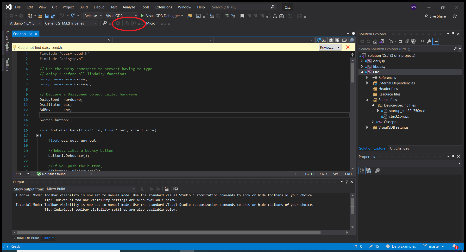
The deploy options seem disabled.
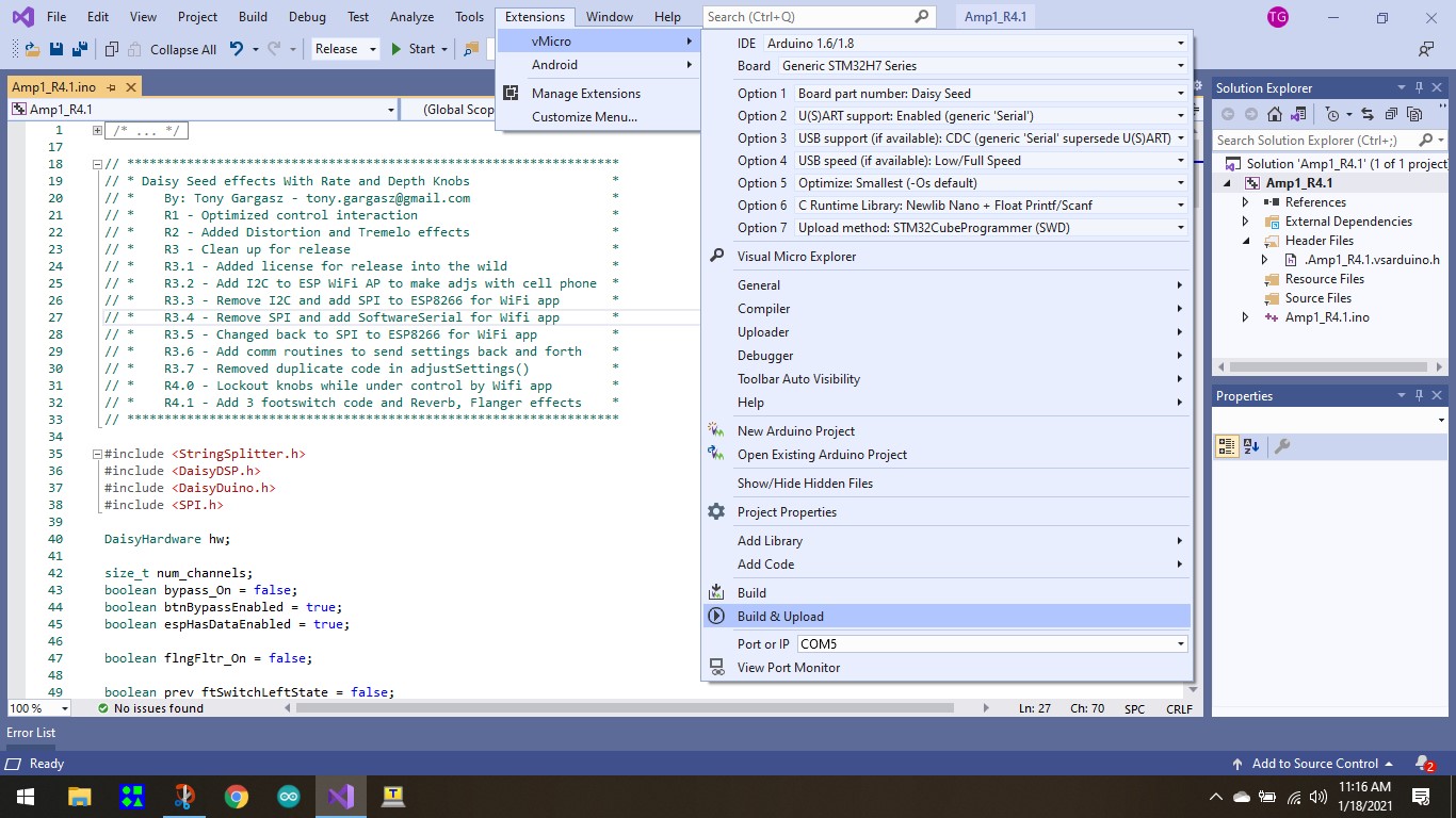
@Deeek777, the build and run commands are located in the vMicro menu. Click Extensions on VS main menu and select vMicro. You will see Build and Build/Upload and Run near the bottom just above port selection. vMicro has settings that allow you to display those options as a toolbar.
1 Like
It appears you seem to be attempting to build different types of programs using different extensions/build systems.
@TGargasz is using vMicro for Arduino development inside of Visual Studio.
Meanwhile, @Deeek777 is attempting to build a VisualGDB project using libDaisy. (which are not compatible with Arduino or vMicro).
If you’re trying to use vMicro+Arduino, then you will need to use the DaisyDuino library for Arduino. You can validate your setup on one of the many DaisyDuino Examples.
Hope that helps!
1 Like