Hello all, I’m trying to bring an idea from the synth world into the pedal kingdom, and want to understand (what I guess are) some core concepts first… I’m guessing this is basic stuff for most here. It’s mostly about adding CV/Expression input, and I’ve been looking at the schematic from the ES Daisy Patch, and wanting to adopt the CV input/knob combo idea to bring into a custom Daisy board of my own.
- I’d like to use a standard 9V DC pedal power supply.
- Schematics that I see for modular synth gear use +12V and -12V
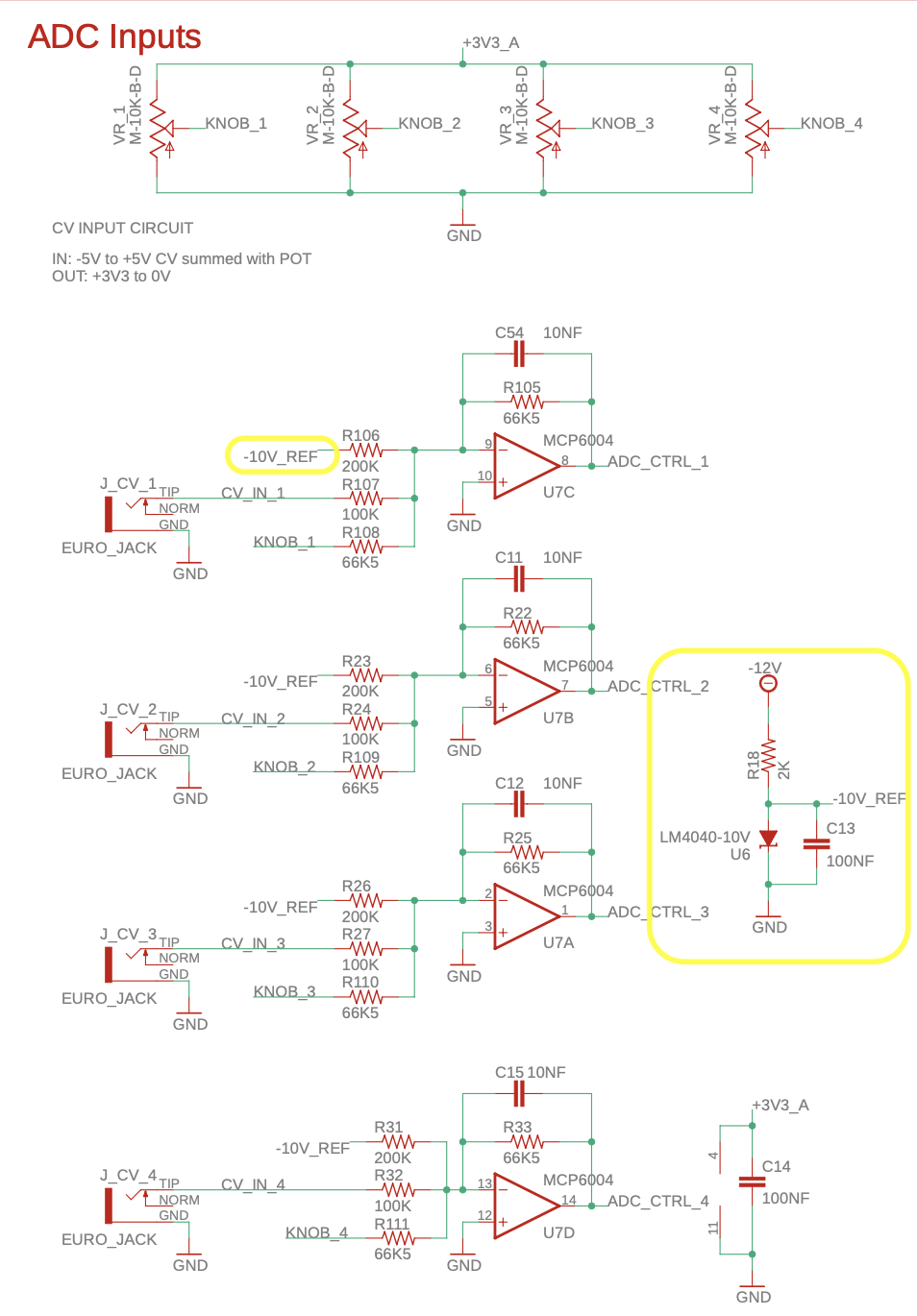
- The CV inputs on the Daisy Patch use a -10V reference from a shunt voltage reference (LM4040)
Questions for bigger brains:
- Why do modular systems use positive and negative voltages, and pedals only seem to use positive?
- For CV or expression inputs, how is the needed reference voltage decided? Meaning, the ES Daisy Patch uses a -10V reference. Could a -9V or +9V reference voltage work the same way? Or a +5V?
I’ve attached a bit of the Patch schematic, and highlighted the parts that I don’t quite know how to translate to a 9V DC circuit. Any help, education, complaints, suggestions, or guidance would be greatly appreciated! Thank you!
Thank you for that explanation! I was able to glimpse before it disappeared, that was very helpful.
You can still look at it by clicking on the pencil-history icon at the upper right. I was wondering why the deletion, since it seemed relevant-helpful-accurate, except for the (perhaps humorous?) part about “since the beginning of time”.
2 Likes
I decided to pull it, just in case I was mistaken…
Neat trick about the edit history!
Here it is:
Pedals, since the beginning of time, used one 9v battery, or a power supply equivalent. The signals between a guitar and amp are small, so a maximum voltage swing of a bit less than +/-4.5V is more than enough.
Synths commonly handle much larger voltage swings.
The reason for the -10v reference in that circuit is to produce the behavior defined in the small print above the schematic. Specifically: input of -5 to +5 will produce output of +3.3 to 0. Note the inversion.
Using -9 instead of -10 will change the range of inputs, but, since the inverting (-) input of the op amp is used, the reference must be negative.
1 Like
This would be a good place to suggest using the Falstad simulator to tinker with the circuit, and see what happens.
https://www.falstad.com/circuit/
Ooh! Thanks again! I’ll give the simulator a go…
1 Like