I came with this to buffer the input and output:
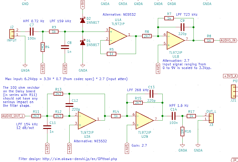
Caution, this was not thoroughly tested. It works on a breadboard but I’m waiting to receive the prototype PCBs to do more extensive tests. Also, off the screenshot, there are 100 nF bypass capacitors between op amps pins 4 and 8. If you care about linearity, use polypropylene or C0G/NP0 ceramic caps. The 100 nF coupling caps can be in (cheaper and smaller) polyester. The +4V5 bias voltage is generated with a bridge made of two 22 kΩ resistors and a 47 µF bypass capacitor.
Also, please note that the input buffer is inverting, so the polarity should be inverted in software if you care about it.
I hope it helps.