Basic question - is the guitar pedal / petal schematic available on github yet? I assume it’s still being worked on, as I don’t see it in in the hardware reference folder. Unless I’m looking in the wrong spot?
It hasn’t been posted yet, but will be posted very soon, along with the petal’s phase of shipping 
1 Like
hi there, just got my Daisy today… very excited to get started… Just wondering, does anyone have the circuit to buffer/attenuate guitar level inputs (as opposed to line level)?
I guess these will be included in the above ‘pending posting’?
I came with this to buffer the input and output:
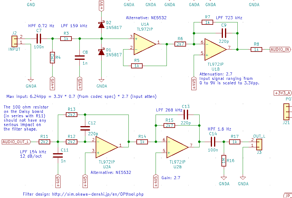
Caution, this was not thoroughly tested. It works on a breadboard but I’m waiting to receive the prototype PCBs to do more extensive tests. Also, off the screenshot, there are 100 nF bypass capacitors between op amps pins 4 and 8. If you care about linearity, use polypropylene or C0G/NP0 ceramic caps. The 100 nF coupling caps can be in (cheaper and smaller) polyester. The +4V5 bias voltage is generated with a bridge made of two 22 kΩ resistors and a 47 µF bypass capacitor.
Also, please note that the input buffer is inverting, so the polarity should be inverted in software if you care about it.
I hope it helps.
1 Like
Hey that’s awesome! I’ll get this on a breadboard asap. Thanks, Will
The Daisy Petal schematic files are now live on GitHub!
2 Likes
Sorry for the new post on an old thread, but I am brand new to DaisyLand. I am struggling to get with the programing, but the electronics around the edges are in my wheelhouse. Some comments:
The above schematic from Firesledge is probably overly cautious about input protection, with Schottky diodes D1 and D2. I worry that their reverse leakage current could cause the op amp output to not stay at the 4.5V virtual ground, given the high DC impedance. It probably still works, but the headroom will be reduced. The low-pass caused by C8 to ground is 159KHz only if the upstream device is low impedance. A guitar pickup is not. I would nix C8 altogether. Also, it is best practice to have a large (say 2Meg) resistor to ground directly on the input. This eliminates the possibility of a pop if this circuit is wired up to a true bypass stomp switch. Then again C7 is small enough that it will not be severe. On the output, C14 should be way bigger than 100n. Best practice is that guitar pedals should have low output impedance, just in case they are not driving another high impedance pedal or amplifier input.
The Daisy Pedal schematic is more typical:
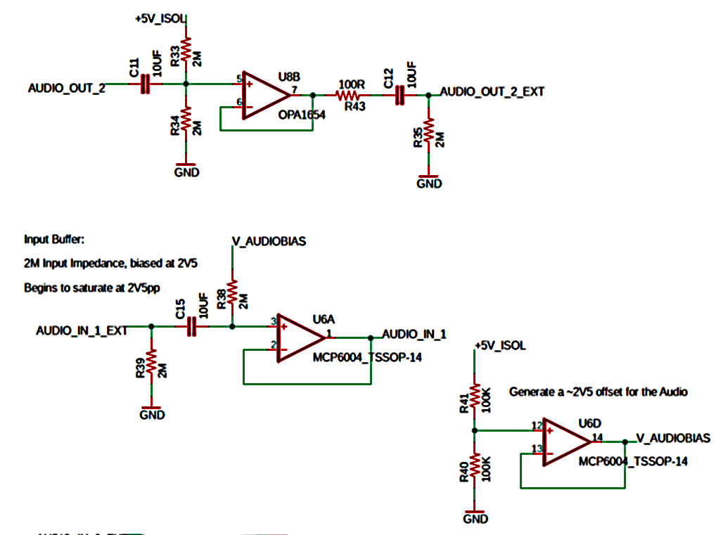
On the input, C15 is way too big - it should be more like the Firesledge’s 100n. Small correction: the input impedance is 1M, not 2M, due to the parallel combination of R38 and R39. On the output, R35 could be smaller like 10K or at most 100K, in case C12 or the downstream device is leaky. Again this will insure no pops in true bypass. Also, I always put a cap to ground on the dividers for virtual ground(s), like across R40 in the pic, to keep it as quiet as possible.
Some of this is quite nit-picky. But I believe that everyone wants their Daisy devices to be as good as they can be.
Don
1 Like
You’re totally right! I revised my schematics in the meantime and forgot to report the changes on this forum. I swapped C8 with C9 (220 pF / 1 nF) to take into account the high impedance of the input and added a 2M2 resistor tied to ground just before C7.
I will fix the 100 nF output too. I forgot that people may want to plug their pedal directly on regular line inputs.
1 Like
What is the purpose of the 2.5V audiobias here? Doesn’t the daisy seed datasheet say that the absolute min/max voltage going into the Audio_IN pin should be -1.8V-1.8V (3.6Vpp)?
Also, is there no need for a preamp in this scenario?