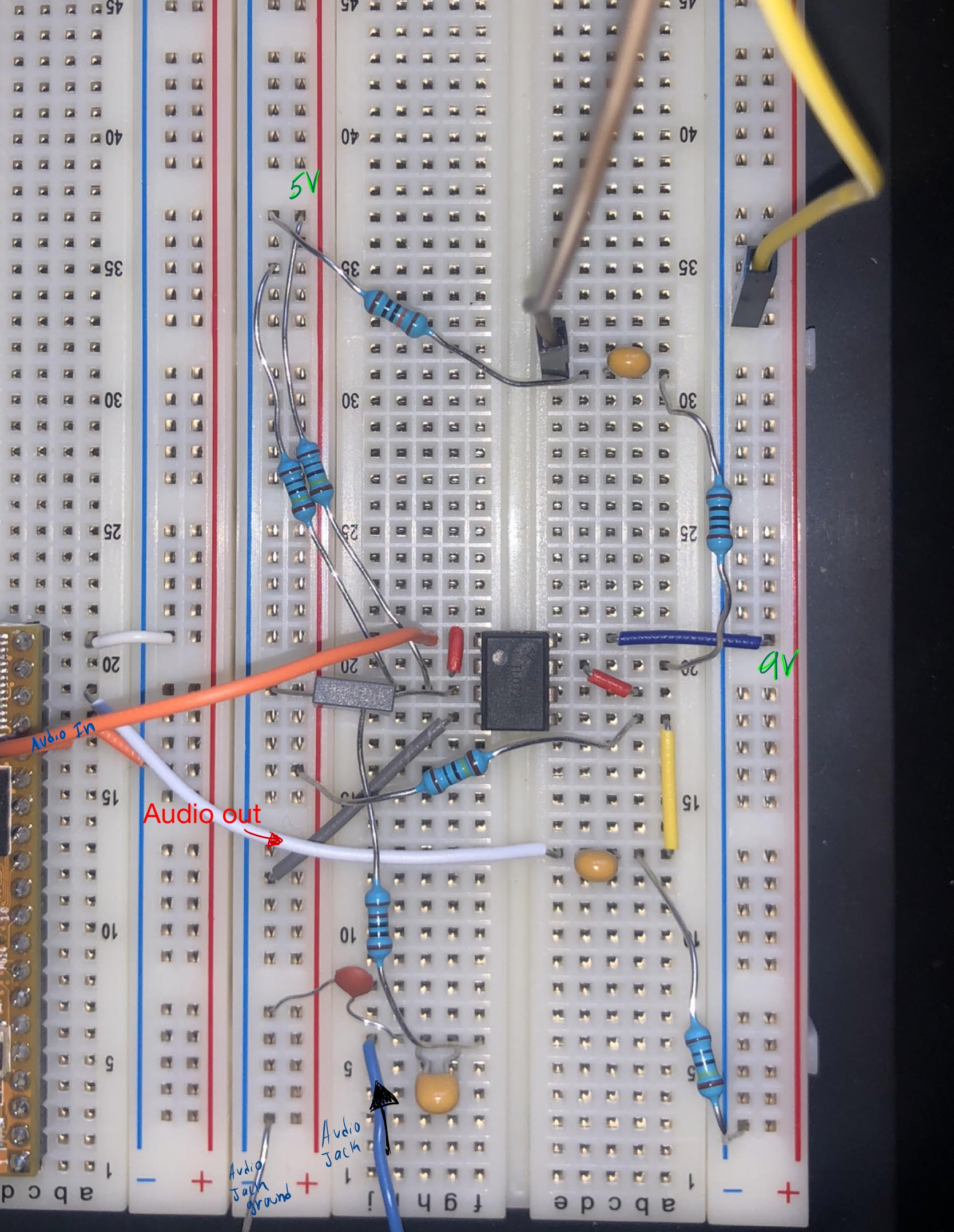
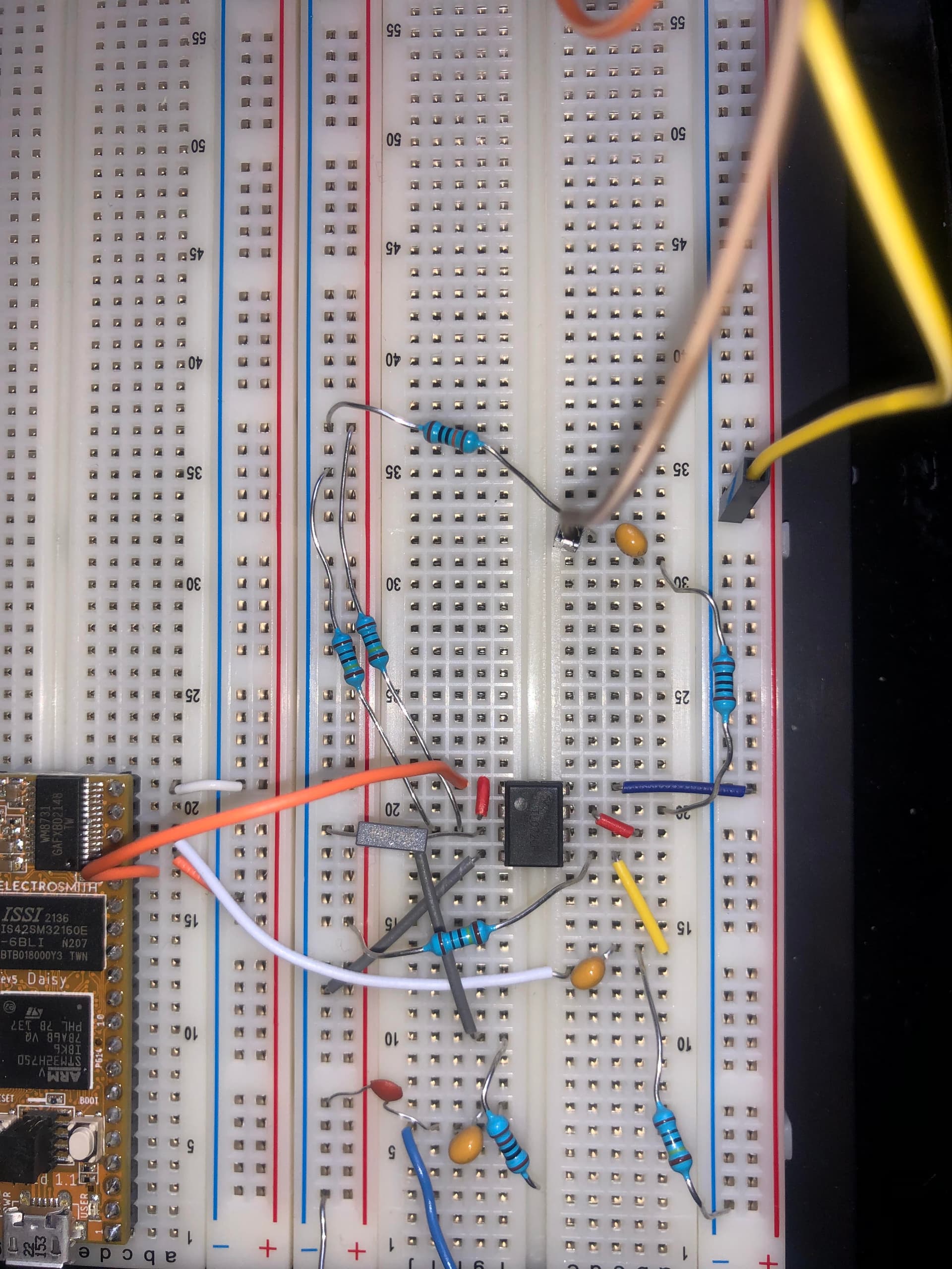
Hello! I just got my daisy seed and I’m working on the input and output buffer using the terrarium schematic from pedalPCB. I have it all wired up but I’m wondering if I’m doing it correctly before proceeding. I have provided a picture of my wiring and tried to make some helpful labels. Also, I see on the schematic that some resistors are wired to 5V and so my plan is to run 5V into the positive rail on the left for the resistors and 9V to the other positive rail on the right to power the TL072, is this the correct way to do it or will I break something? Sorry if it’s messy and if my questions seem basic, this is my first time working with hardware and following a schematic.
1 Like
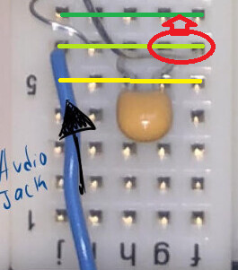
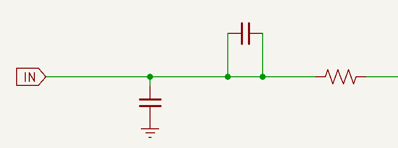
All holes in the row are connected.
(I drew the yellow and green lines to illustrate the row connections.)
That capacitor is mounted with both leads in one row.
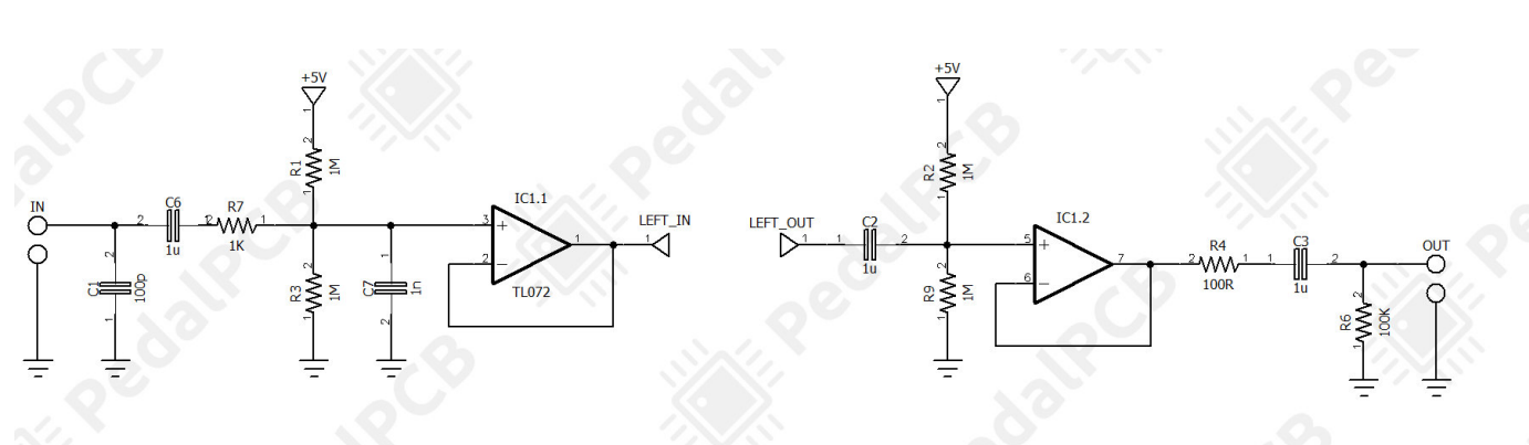
The schematic would look like:
That’s not how it is on the schematic you posted.
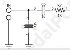
You can move the right lead of the capacitor one row up (g6 to g7), and the resistor in f6 moves to f7
Also, be careful when crossing leads that are not isolated, accidentally making a short.

Instead, wire the resistor to an empty row(one end is moved to f7 - the other end in f9 (or another empty row - continue using insulated wire from g9 to j19).
I haven’t looked at the rest. But it seems you have made similar errors involving c13-d13, b31-c31
1 Like
Thanks for your feedback and your illustration it was really helpful. I think I fixed the issues you pointed out, here is an updated picture.
Also, add a 0.1uF capacitor between pin 8 of the IC and ground.
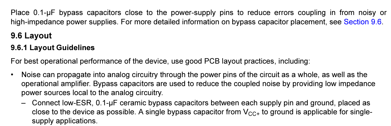
from p36 of the TI datasheet
I won’t guarantee that there are no other errors, but it looks OK to me now.
2 Likes
Thank you again, I got it working!
2 Likes