I’ve been working on a new pedal design for the Daisy Seed. I really enjoyed using the Hothouse but wished it had more controls so I built a new pedal design. First and foremost I wanted this for myself but I want to gauge the community’s interest in making this available to a larger audience. I have SMT board and enclosure prototypes made and working. My day job is as a software engineer so writing the firmware was the easiest part for me. It’s based on the format that most of the Daisy hardware drivers use. I’ll open source that when the time comes.
The pedal has lots going on so here are the details.
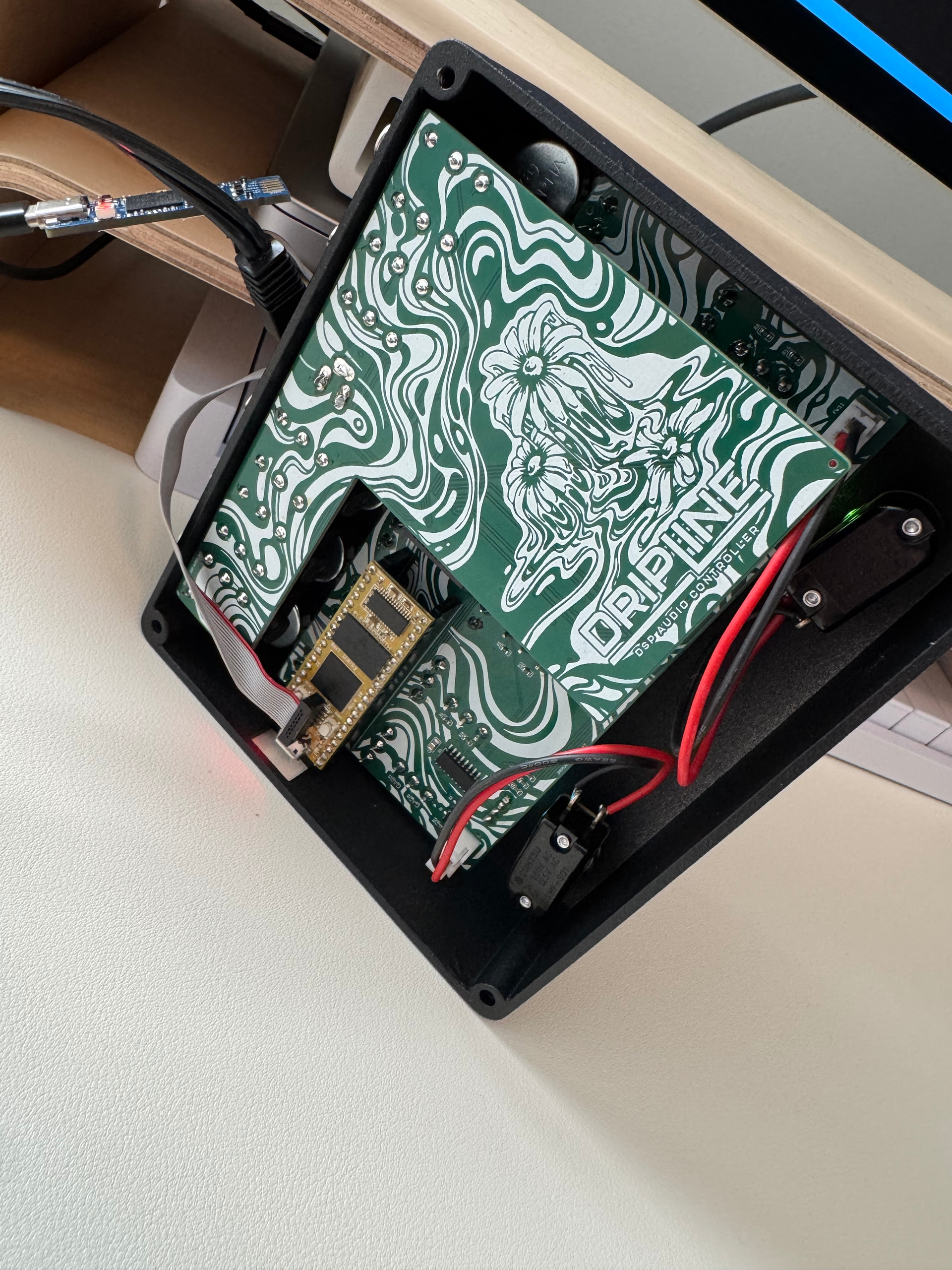
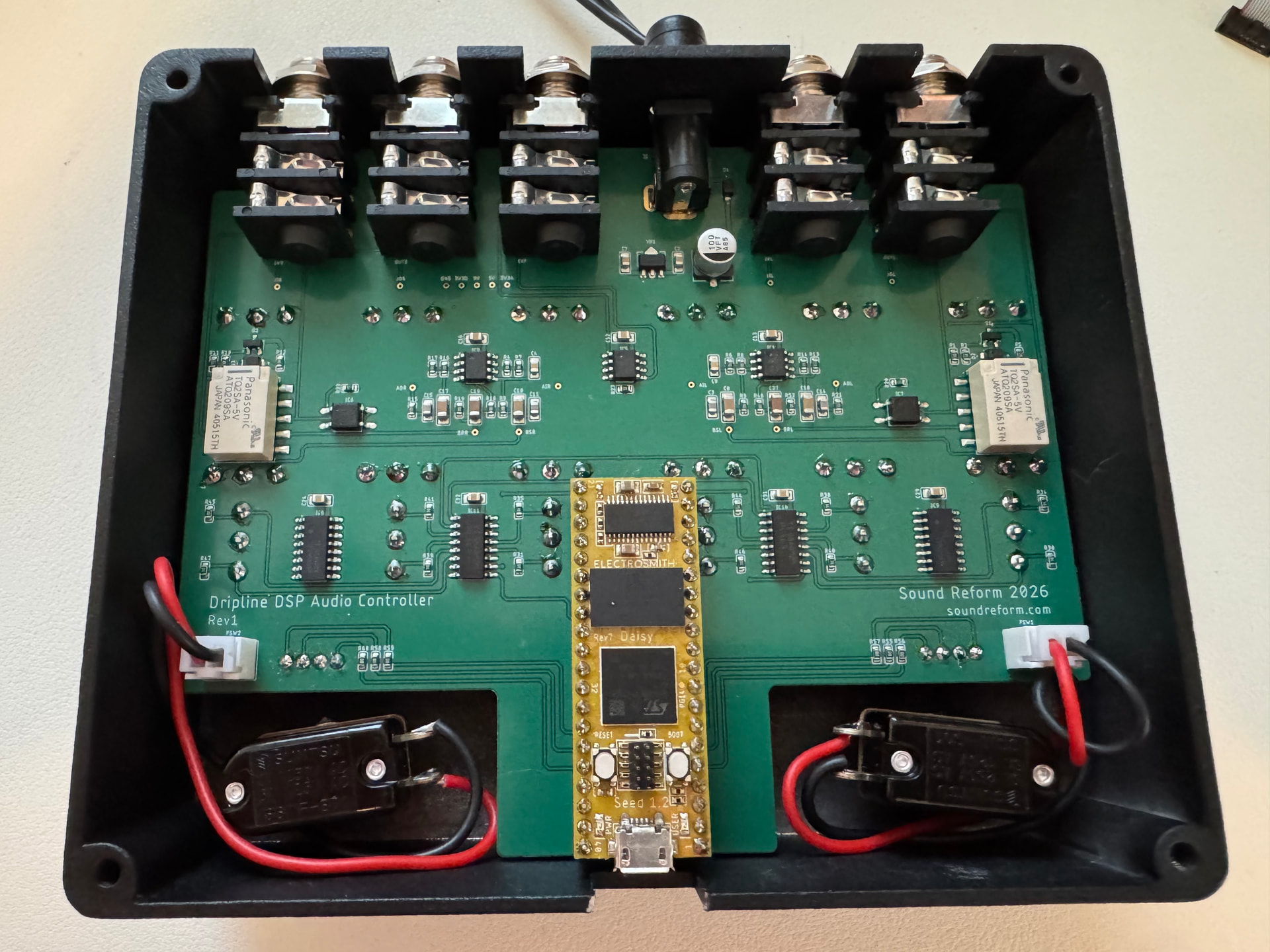
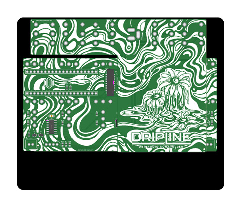
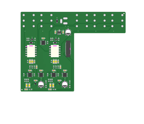
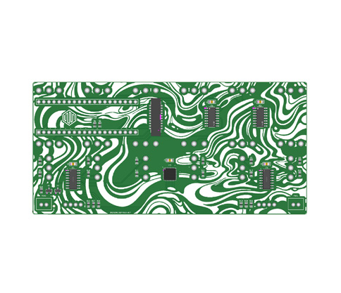
This design utilizes two boards; one handles the 1/4 jacks, power and audio circuits. The other handles the controls and Daisy. The boards are connected using an IDC connector.
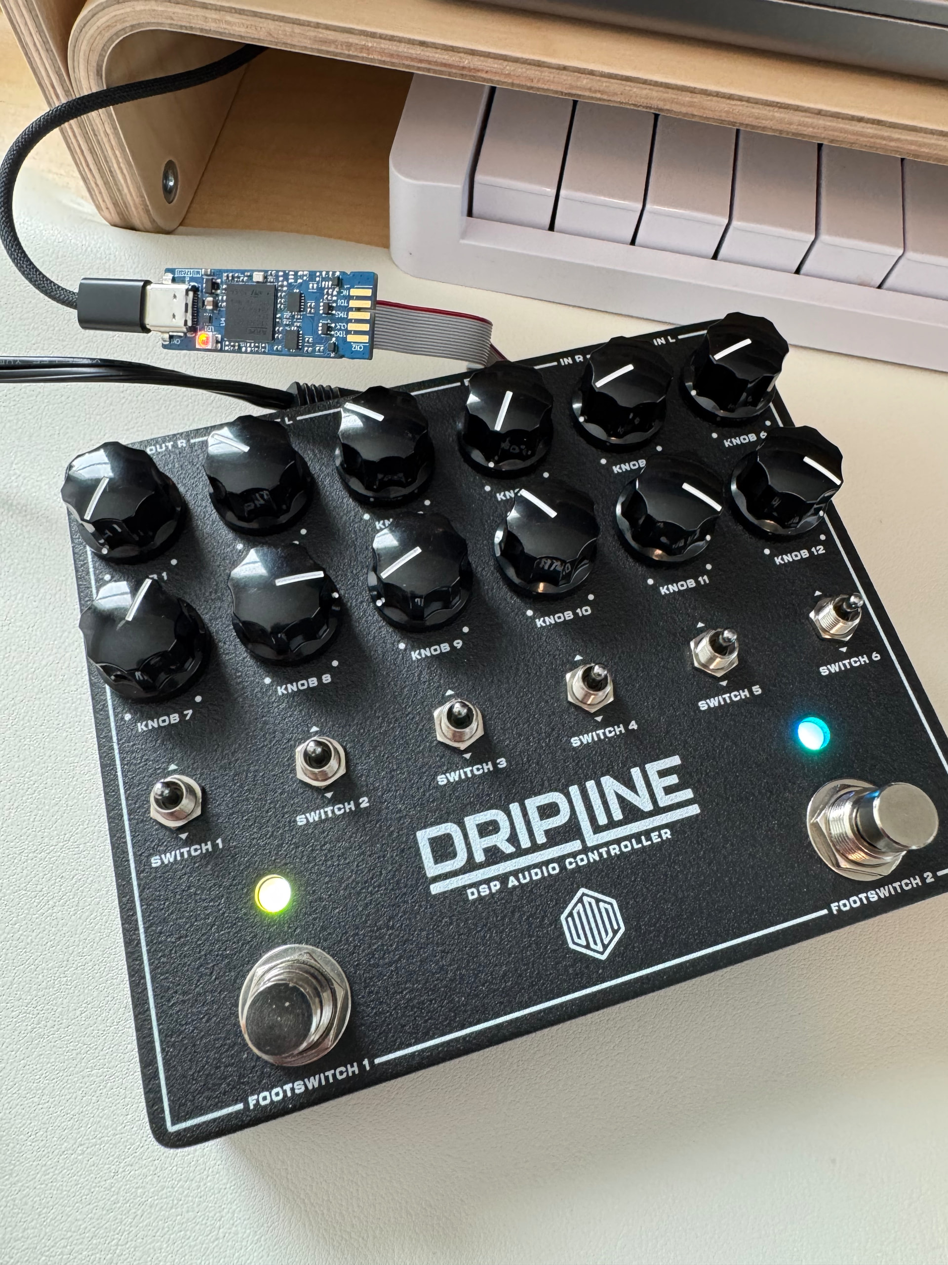
Enclosure
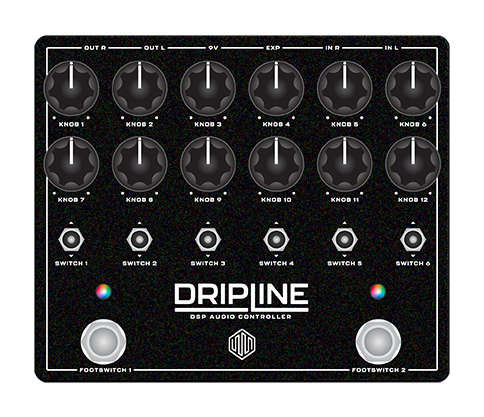
1590XX style enclosure with a matte finish and custom silkscreen.
Knobs
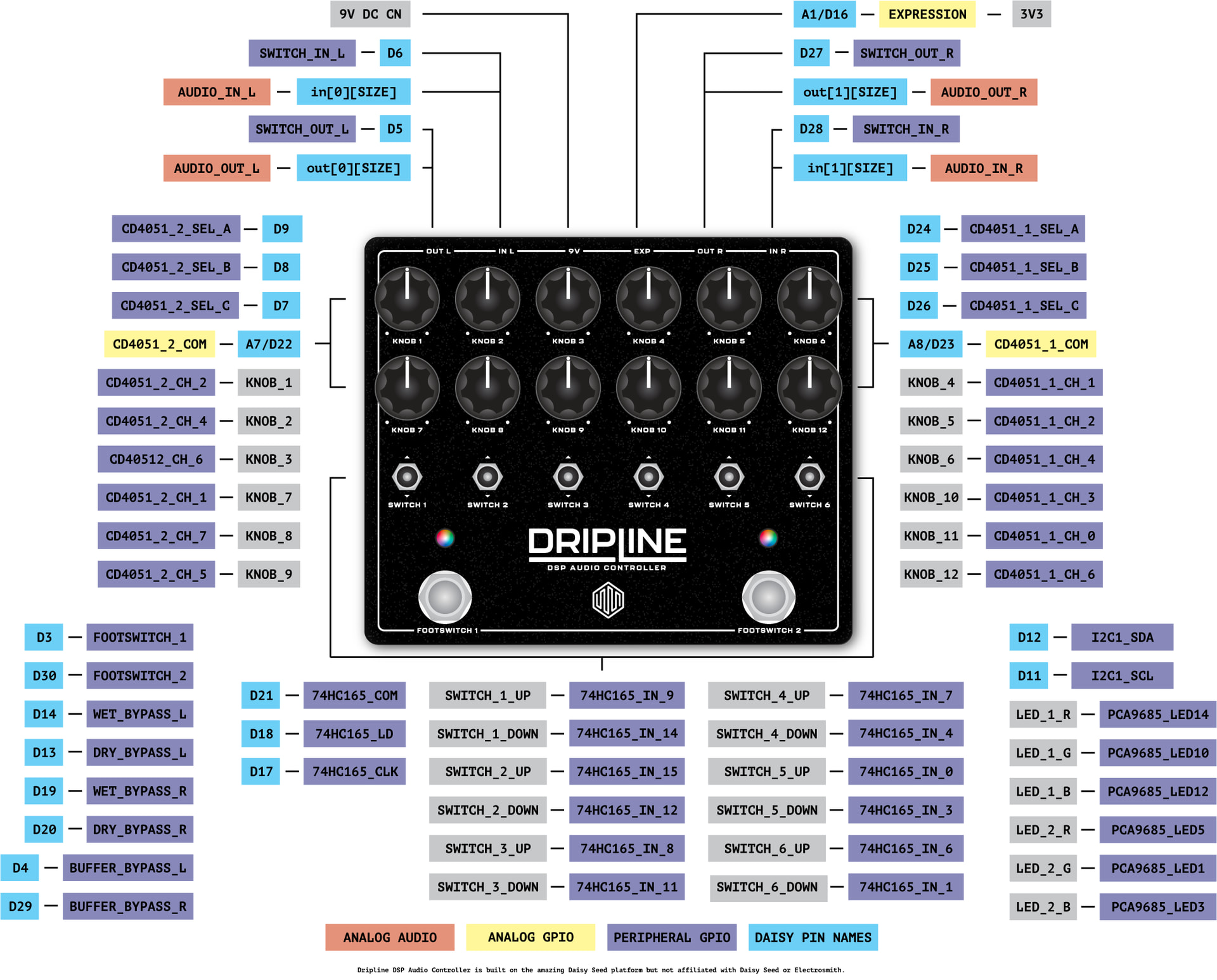
12 16mm alpha pots connected to two CD4051 analog multiplexers. These use the built-in analog control mux driver.
Toggle Switches
6 SPDT Taiway switches connected to two 74HC165 shift registers. These use a custom driver but could probably be contributed upstream if there is interest.
Leds
2 5mm RGB Leds connected to one PCA9685. These use the built-in LED driver.
Footswitches
2 Pro-Grade SPST Momentary Foot Switches (Normally Open, Soft Touch) are wired to the main board using JST connectors.
Input Jacks
2 1/4" switched stereo jacks for separate left and right channels. The ring is connected as a switch and can be used in code to tell if something is plugged into the jack. The switch of each channel’s tip is connected to the other channel so you get an analog signal on the channel that is not connected.
Output Jack
2 1/4" switched stereo jacks for separate left and right channels. The ring is connected as a switch and can be used in code to tell if something is plugged into the jack.
Expression Jack
1 1/4” switched stereo jack for expression input. The tip takes a 3V input and passes it through a buffer before sending it to the Daisy. The ring provides a stable 3V output. You would typically connect the ring and tip to an external expression pedal/pot to control the voltage.
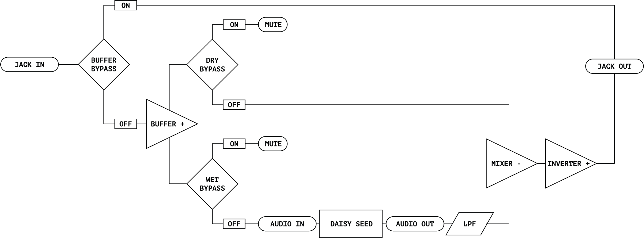
True Bypass
The pedal comes with two relays to provide true bypass of both the left and right channels. When bypassed the input and output jacks are connected directly.
Tails/Trails Bypass
The pedal comes with four analog IC-based switches. These allow you to bypass the buffered signal going into the Daisy for each channel. The other two switches let you bypass the buffered dry signal from mixing with the Daisy’s audio out. Used in tandem, you can have trailing bypass by disabling signal input into Daisy’s audio in and enbling buffered dry output. If you don’t want to mix the dry and wet signals in software this configuration enables mixing the buffered dry signal with the Daisy’s wet output.
If anyone is interested in something like this existing, let me know!