Had my daisy patch SM for a while and fallen in love!
I was wondering whether it would be possible to combine a potentiometer and CV Input (Jack), into a single CV available pin to get a few more controls. Ideally the combination would work as follows:
When nothing is connected to the CV input the pot works as a 0/100% parameter control, when the CV Input has something connected the potentiometer then functions as an attenuator for the incoming CV signal.
This might be huge wishful thinking without the extra components, obviously with the above examples the signals are combined with an Opamp, but the Daisy patch SM doesn’t require any extra buffering of signals and can take in/out directly from a jack/pot so would it just be a case of connecting the two to an available CV pin(1-8)?
This might only be possible with extra SPI parts but thought it might be worth asking the question before potentially reinventing the wheel!
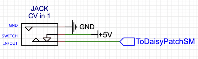
After some theorising; I guess another way this could be possible is by connecting the switching pin (sorry, not sure of the technical name…) to the voltage source like so:
There would be a potentiometer between this circuit and the patch SM, so that when there’s nothing connected to the jack it will get the voltage source, which can then be attenuated by the pot. Then when the CV source is inserted it swaps allowing the CV can be attenuated.
Might seem pretty simple but my main worry is: now for a brief period inserting a jack will combine the CV output with the voltage source?
After inspecting a eurorack cable, the top part of the metal jack is the part that breaks the +5v connection, so the lower part will never touch it or be danger of getting a 5v shock…
Sorry for my stupidity but hopefully someone else will find this useful!
Hello,
I am not into designing electronics ,but your question sounds like what is done with the inputs of terminal tedium from mxmxmx. The schematics are available on GitHub.
Hope this can help you.