I have just assembled the second revision of my prototype module. The first revision matched the Daisy Patch schematic very closely. The second revision makes a few changes, but nothing too major.
One thing I changed was the pin assignments for the push encoder. The encoder increment/decrement is working as expected, but unfortunately the switch is not working. The switch will actually register one press, but not any subsequent presses.
I probed the encoder pins, and when the encoder is in the unresponsive state, pin D on the encoder (ENC_CLICK in the Patch schematic) is connected to ground.
This appears to be some kind of configuration issue, because when the module is powered off pin D is not connected to ground. Also, Pin D is connected to the expected GPIO pin on the Daisy Seed. It seems like something is overriding the pull-up behavior of the GPIO pin I’m using, but I’m not really sure.
I haven’t changed the encoder initialization from the previous revision (apart from remapping the pins), so I’m not sure what is going wrong.
Does anyone have any suggestions?
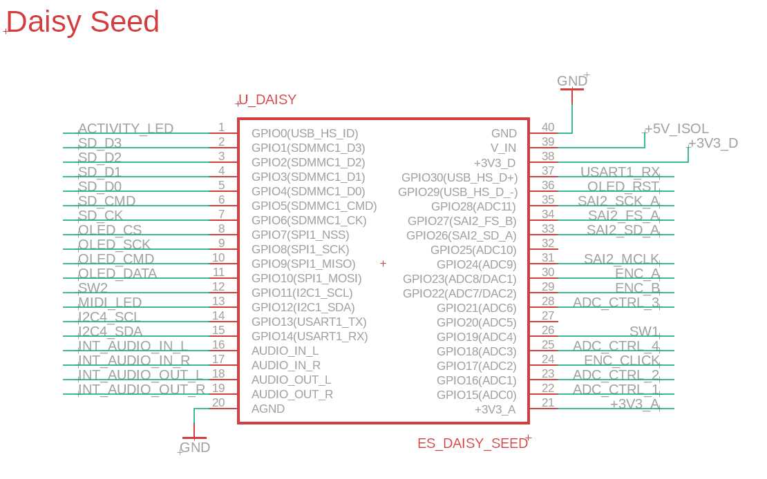
Here are the pin assignments for my board:
#define PIN_ENC_CLICK    17
#define PIN_ENC_B        22
#define PIN_ENC_A        23
#define PIN_OLED_DC      9
#define PIN_OLED_RESET   29
#define PIN_MIDI_IN      30

#define PIN_SAI_SCK_A    28
#define PIN_SAI2_FS_A    27
#define PIN_SAI2_SD_A    26
#define PIN_SAI2_SD_B    25
#define PIN_SAI2_MCLK    24

#define PIN_CTRL_1       15
#define PIN_CTRL_2       16
#define PIN_CTRL_3       21
#define PIN_CTRL_4       18

#define PIN_SW1          19
#define PIN_SW2          11
#define PIN_MIDI_LED     12
#define PIN_ACTIVITY_LED 0
Follow-up: I’ve found that if I call InitEncoder() again in my application (which requires making it a public function) after all of the other initialization steps, then the switch works. So something seems to be resetting the GPIO configuration for the ENC_CLICK pin. But I’m not sure what might be doing that.
Hey miminashi,
Using pin D17 for encoder’s CLK pin is perfectly fine.
Could you share the other changes that you made to the second revision PCB as well as the code itself?
It seems like the code is causing the issue?
And I have an encoder connected to a Daisy Seed (with the CLK pin connected to D17) so if you would like me to test something out, please feel free to let me know. There are only encoder, input jack, output jack, and LED connected.
This is how I’ve assigned all of the pins on the Seed:
I’ve found the code that is affecting the encoder. I am reconfiguring the USART to use interrupts instead of DMA, and somehow this is affecting the configuration for the encoder click. I’m not sure yet which steps are messing things up, maybe the CLK_ENABLE calls or maybe the HAL_GPIO_Init calls. I’ll have to dig a little deeper.
[edit]: It is the HAL_GPIO_Init calls. I wonder why they are conflicting with GPIO17.
void initializeUSART_HAL(USART_TypeDef* usart)
{
    __HAL_RCC_GPIOB_CLK_ENABLE();
    __HAL_RCC_USART1_CLK_ENABLE();

    // Init Pins
    GPIO_InitTypeDef GPIO_InitStruct;
    GPIO_InitStruct.Mode      = GPIO_MODE_AF_PP;
    GPIO_InitStruct.Pull      = GPIO_NOPULL;
    GPIO_InitStruct.Speed     = GPIO_SPEED_FREQ_LOW;
    GPIO_InitStruct.Alternate = GPIO_AF7_USART1;

    // Setup TX pin
    {
        GPIO_TypeDef* port  = GPIOB;
        GPIO_InitStruct.Pin = 6;
        HAL_GPIO_Init(port, &GPIO_InitStruct);
    }

    // Setup RX pin
    {
        GPIO_TypeDef* port  = GPIOB;
        GPIO_InitStruct.Pin = 7;
        HAL_GPIO_Init(port, &GPIO_InitStruct);
    }

    UART_HandleTypeDef huart = {};
    huart.Instance                    = usart;
    huart.Init.BaudRate               = 31250;
    huart.Init.WordLength             = UART_WORDLENGTH_8B;   // 8
    huart.Init.StopBits               = UART_STOPBITS_1;      // 1
    huart.Init.Parity                 = UART_PARITY_NONE;     // none
    huart.Init.Mode                   = UART_MODE_RX;         // RX/TX?
    huart.Init.HwFlowCtl              = UART_HWCONTROL_NONE;
    huart.Init.OverSampling           = UART_OVERSAMPLING_16;
    huart.Init.OneBitSampling         = UART_ONE_BIT_SAMPLE_DISABLE;
    huart.Init.ClockPrescaler         = UART_PRESCALER_DIV1;
    huart.FifoMode                    = UART_FIFOMODE_ENABLE;
    huart.AdvancedInit.AdvFeatureInit = UART_ADVFEATURE_NO_INIT;

    if(HAL_UART_Init(&huart) != HAL_OK)
    {
        errorHandlerMsg("[ERROR] Unable to initialize USART\r\n");
    }

    // Configure the RX/TX FIFO
    HAL_UARTEx_SetTxFifoThreshold(&huart, UART_TXFIFO_THRESHOLD_1_2);
    HAL_UARTEx_SetRxFifoThreshold(&huart, UART_RXFIFO_THRESHOLD_1_4);
    if(HAL_UARTEx_EnableFifoMode(&huart) != HAL_OK)
    {
        errorHandlerMsg("[ERROR] Unable to configure FIFO for USART\r\n");
    }

    __HAL_UART_ENABLE_IT(&huart, UART_IT_IDLE);
    __HAL_UART_ENABLE_IT(&huart, UART_IT_RXNE);
    __HAL_UART_ENABLE_IT(&huart, UART_IT_RXFF);
    __HAL_UART_ENABLE_IT(&huart, UART_IT_RXFT);

    HAL_NVIC_SetPriority(USART1_IRQn, 0, 0);
    HAL_NVIC_EnableIRQ(USART1_IRQn);
}