Hi,
I’m going to connect my new Daisy patch to my modular rack system.
I would like to avoid to damage it, and I’m also writing a cheatsheet with specific information about the hardware/software.
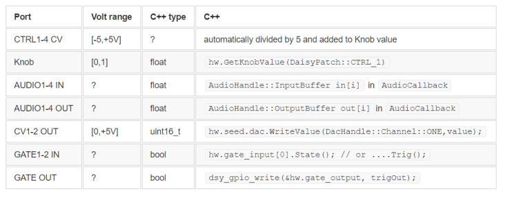
I would like to complete the following table (I’m not an electronic expert and I didn’t find the information on the documentation):
- What are the valid Audio Input , Audio Output and CV Output voltages?
- What are valid voltages for the gate inputs and what voltage is written when switching on the output gates?
- Furthermore the CV outputs write function is called using an uint_16; what is the formula to convert it to the effective output voltage?
Thank you in advance!
Hi @algoritmarte
Here’s a bit of detail to fill in your table:
CTRL 1-4: These are read into the AudioControl class and will output a value 0 to 1 corresponding to the knob position.
The CV input adds to the knob position. So with the knob fully fully counter-clockwise a positive 0-5V CV signal will move the control from 0 to 1, and with the knob fully clockwise, a negative 0 to -5V signal will move the control from 1 to 0.
Audio Input/Output will clip at 20Vpp (+/- 10V), but the intended signal range that corresponds to a normalized +/- 1.0 in software is 10Vpp (+/- 5V)
Gate Input circuits are BJT transistor driven, and will toggle at a very low threshold (~300mV or so if I’m remembering correctly), and can accept signals within the Eurorack power rails (+/- 12V) without issue.
The Gate Output circuit is identical to the DAC output circuits and outputs 0-5V
The conversion from uint16_t to output voltage is roughly:
output_voltage = (dac_code / 4095.0) * 5.0
Hope that answers all your questions! 
3 Likes
Great, it’s very useful, now I have a clearer idea of the whole system and I’ll publish the cheatsheet on github!!! (and yesterday I managed to create my first “algorithm” on Daisy)
2 Likes
Glad to hear it! Can’t wait to see what you do with the Daisy!