I’m a little confused by the daisy seed pinout.
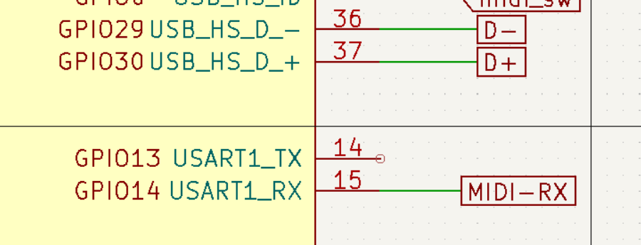
usart1 RX appears on pin 37 and on pin 15.
How is that managed ?
At the moment, UART config is still fairly limited through libdaisy (i.e. only the primary UART1 is implemented).
When we get around to adding the multi-peripheral support (like in I2C, etc.) you will be able to use either pin for UART1 Rx. The STM32 has many alternate functions for various pins, and there are several that overlap to allow for more flexibility when desigining hardware.
This will be fairly transparent through libdaisy. You’ll be able to pass either pin to the config struct, and it will automagically assign the correct alternate function configuration, etc. for that pin.
2 Likes
I’ve been looking at the USART too, as a means of communicating bettween a number of Daisies. More functionality in libdaisy would definitely be appreciated!
I found the pinout diagram a bit confusing too. From the tests I’ve been doing on transmitting it appears that calling UartHandler::PollTx() sends data out on pin 14 and nothing on pin 36.
MidiHandler in Midi.h seems to be using pins 14 and 15 too.
So I’m assuming that pins 14 and 15 are the ones to use for USART1 for now.
1 Like
I can see why there was some confusion on the pinout. The inner-most features are the mappings that were added to libdaisy first and were often hard coded. This is slowly changing (I2C has support for multiple peripherals now, and more are coming as well) so that multiple peripherals and any of the pins available can be used for them.
U(S)ART is one of the next planned for this expansion. For now, (hardware) pins 14 and 15 are the ones set up for this protocol by default.
1 Like
Thanks @shensley,
it works quite fine, now i can experiment with MIDI and try to port a part of my Axoloti code and see how and what is possible with the Daisy Seed (my goal is to have the same palette as the Axoloti but at a 96kHz sample rate, at the moment i use x2 oversampling and a custom /2 decimator to simulate this).
2 Likes
Sorry for necroposting but I just couldn’t find any answers on this other than here.
Is this still the case? Can’t find anything about this in the libdaisy docs
Mainly thinking if I can have a USB-A plug for firmware updates AND a MIDI-RX for these pins:
Edit:
Looked at the schematic for the Daisy POD and it’s indeed using USB for GPIO29 and 30 and MIDI-RX for GPIO-14(pin 15).
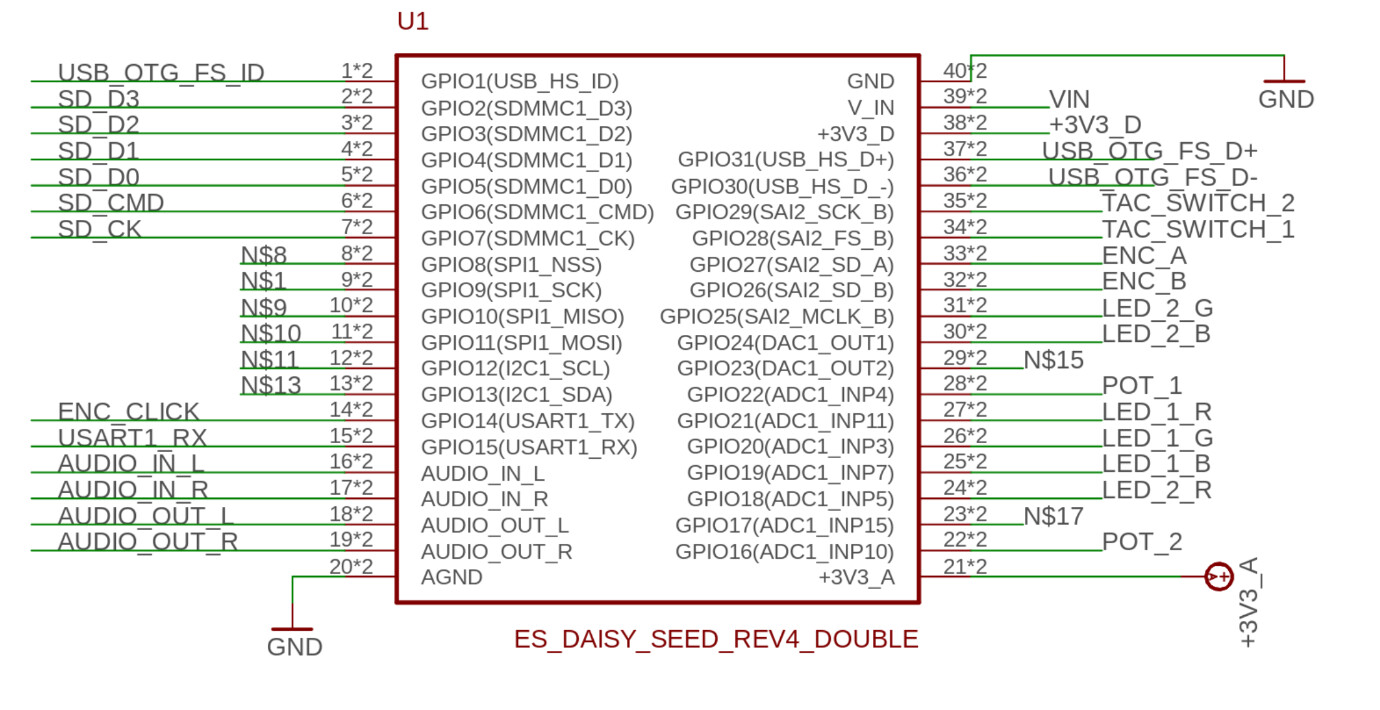
btw the pinout looks wrong in the schematic, it seems like everything is offset by +1 in pin numbers.
Me too i do not really understand how to use two different UART with the daisy seed
OK for the pin 15/16 for the Midi for example.
But a want to use also another UART for a nextion screen Pin 36 and 37
On the schematic these pins are connected to R14/R15 port
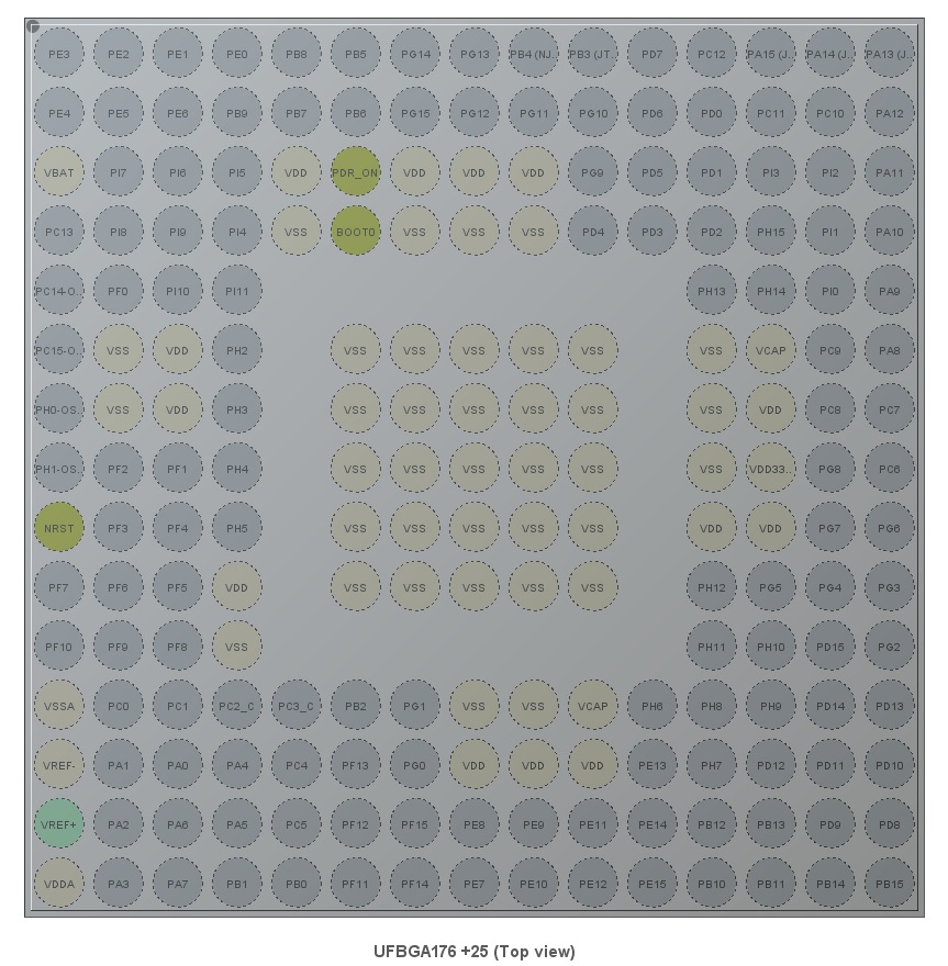
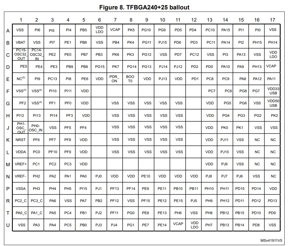
But when i open the STM32H750IBK6 data sheet or when i try with a cube MX the pin PR14 and PR15 are not present.
Can i really use the 36/37 for an UART
No really i do not understand.
On the schematic of the daisy seed what are the R14 R15 pins.
R is relatif of the placement of the ball or it is the IO port R ?
Hello Gilles,
Yes, pin 36 can either be used as USB D- or USART1 Tx and pin 37 as USB D+ or USART1 Rx.
Thank you Takumi. I have finish to understand the schematic and the different notation for the H7. But i did not find a way tu use another UART or USART to drive my external screen. Did you have a solution ?
Thank again
Hello Gilles,
If you used pin 14 (USART1 Tx) and pin 15 (USART1 Rx) already for USART1, then you won’t be able to use pin 36 and 37 for USART1s.
So, you’ll need to use another UART peripheral other than USART1. Which one you want to use depends on which pins are open in your project.
By the way, you would need to power the Nextion screen with 5V. Daisy’s output (if you are just powering it via USB port from your computer) is 3.3V so that could be what’s causing your issue. You would need to connect 5 volt externally to the Daisy’s VIN pin.
1 Like
Hi Takumi
Now i have a result.
I use the UART7 for the Tx and UART5 for the Rx.
I have lost a lot of time to understood that even you do not used the Rx part for the UART7 you need to init the pin Rx to a fake pin.
Like this
//Init TX PB4 UART7_TX / AF11 for the Nextion screen - SPI1 MISO Pin n°10
UartHandler::Config       Nextion_Tx;
Nextion_Tx.baudrate      = 115200;
Nextion_Tx.periph        = UartHandler::Config::Peripheral::UART_7;
Nextion_Tx.stopbits      = UartHandler::Config::StopBits::BITS_1;
Nextion_Tx.parity        = UartHandler::Config::Parity::NONE;
Nextion_Tx.mode          = UartHandler::Config::Mode::TX;
Nextion_Tx.wordlength    = UartHandler::Config::WordLength::BITS_8;
Nextion_Tx.pin_config.tx = {DSY_GPIOB, 4};
Nextion_Tx.pin_config.rx = {DSY_GPIOX,0};       // Always define the two pins TX and RX

// /** UART communication initialization */
Nextion_TX_handler.Init(Nextion_Tx);
I hope it will be usefull for someone
4 Likes
Thank you so much for sharing your finding. I appreciate your patience and contribution.
So i have continue to test my project, and now i test the UART TX for the Nextion and the MIDI Rx. They work fine if i test only one UART. But when i configure the Nextion and the MIDI Uart, only the MIDI is working. In fact the Nextion Tx work also, but in non blocking mode
Nextion_TX_handler.BlockingTransmit((uint8_t )Nextion_tx_buffer,s,100); //Nextion_TX_handler.DmaTransmit((uint8_t)&Nextion_tx_buffer[0],s,NULL,NULL,NULL);
For the DMA mode i think the midi rx uses the same DMA channel, so it is impossible to use two UART with DMA.
Takumi, can you confirm please.
And thank again for your help
Hello Gilles!
The way it is set up now, correct. It is not possible to use two different UARTs with DMA.
The UART is hard coded to RX on DMA1_Stream5 and TX on DMA2_Stream4. Two different UART peripherals shouldn’t share a DMA stream.
That being said, you may be able to hack the library a little to configure one of them to use a different stream. I’m not sure which streams are valid, so this will require you to do some digging as well as trial and error if you decide to go that route.
2 Likes
Ok…
Is there a documentation about all the DMA channels use fir the different periphericals ?
Thank again
We unfortunately don’t have any documentations that we made about this topic.
There are some information in the HAL manual:
https://www.st.com/resource/en/user_manual/dm00392525-description-of-stm32h7-hal-and-lowlayer-drivers-stmicroelectronics.pdf
And also in the reference manual:
https://www.st.com/resource/en/reference_manual/dm00314099-stm32h742-stm32h743-753-and-stm32h750-value-line-advanced-arm-based-32-bit-mcus-stmicroelectronics.pdf
Though, they’re really dense and often not helpful, so we recommend Googling as well as debug probing.