I’m trying to get my Patch SM to work with an SD card reader but without success so far. I’m using the example from
DaisyExamples/patch_sm/HardwareTest/HardwareTest.cpp
(located here on github) but the code seems to hang when f_mount() is called.
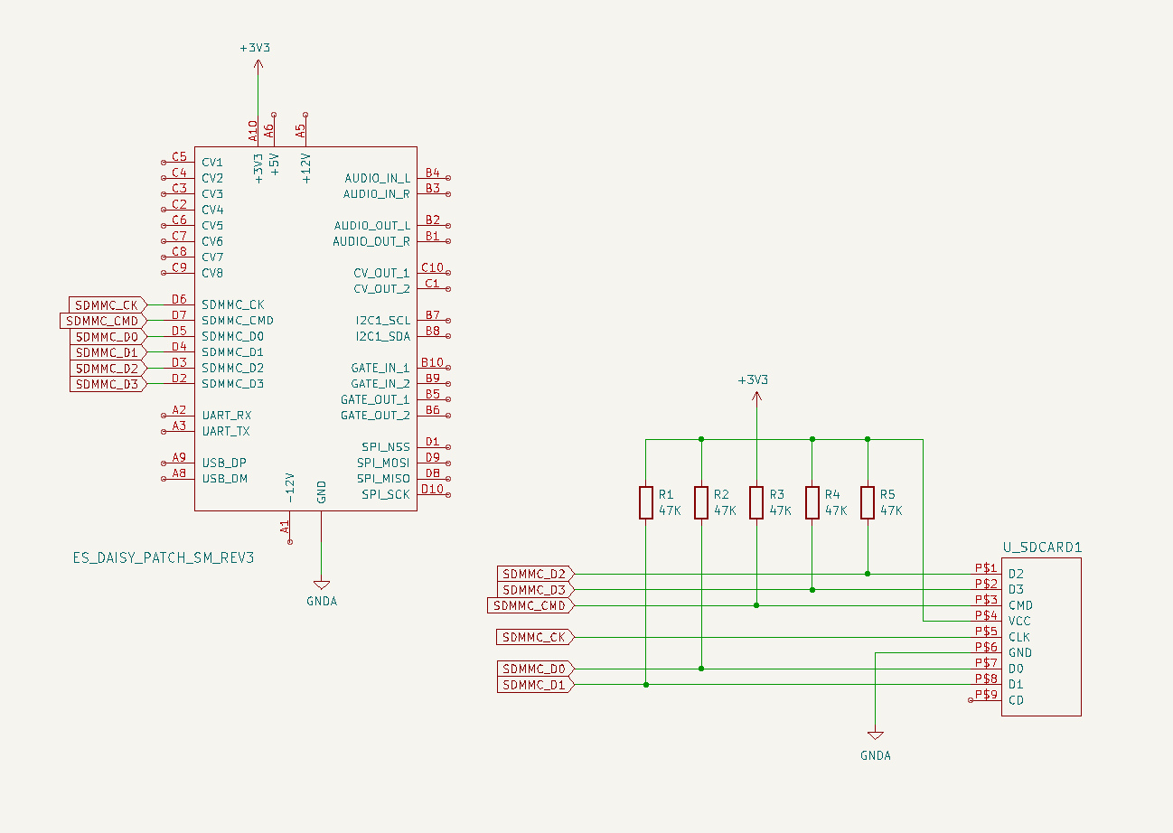
I’m using a 32gb SanDisk SD card formatted with FAT32 and the wiring diagram is as follows:
I’ve also tried removing the pullups to see if it made a difference but that didn’t work either. Has anyone else got the Patch SM working with an SD card using the standard example or any other code?
Hi,
Your schematic connections look okay.
The PatchSM does have 47k pullups on board for the SD card. So you shouldn’t have to add more.
How are you connecting the SD Card connector to the patch SM?
The SD card communications are pretty fast signals, and can be sensitive to long wires, etc. even at the slower speeds used during initialization.
Another helpful bit of info would be the FRESULT returned by f_mount.
You could edit the example to print the f_mount error by doing something like:
FRESULT mount_res = f_mount(&fsi.GetSDFileSystem(), "/", 0);
if(mount_res == FR_OK) {
  . . .
} else {
  hw.PrintLine("Mount Error: %d", mount_res);
}
The number will correspond to one of the FRESULT values in the FATFS API, and will be helpful in further diagnosing what might be wrong.
1 Like
Thank you for your reply and apologies for not replying sooner. The issue was (I think) related to a high data transfer rate over jumper wires. Slowing the speed by itself didn’t work but the following did:
sd_config.speed = SdmmcHandler::Speed::SLOW;
sd_config.width =  SdmmcHandler::BusWidth::BITS_1;
1 Like
Glad to see you got it to start functioning!
At this point, if you haven’t already, you could begin experiment with increasing the speed in 1-bit mode to see if it still behaves as expected.
If so, you could reconnect the other 3 datalines double checking the wiring to see if 4-bit mode would work.
If you still can’t get 4-bit mode working (and still want to) a good next step would be checking if those pins are actually strobing when they’re expected to.
The easiest way of doing this is either with a scope or logic analyzer, but as a quick check you could wire a resistor->LED to them and see if it’s lighting up or not.
1 Like