So, I’m sure these are probably vary basic questions, but I’ve been searching and hoped to ask the community here for some clarification if I could? I’ve done a custom board and JSON with success so far, but have never incorporated any CV elements. I’m hoping to add CV in and outs on my next project. I’ve been trying to do my homework, but am still wondering about a couple of things…
I’ve only used toggles, LED’s, and potentiometers so far, and all of these connected directly to a Daisy pin. Can we do the same with a CV in or out? Or does the CV signal need to be buffered in some way? I tried studying the Patch schematic, where an MCP6004 is used. Is that necessary?
Do CV in and out need an ADC pin? Or will any available GPIO work?
I’ve read discussions recently about wanting more CV outputs than inputs, and I’m just realizing I don’t know if there’s a reason to limit CV outputs to only two per Seed? I’d love to do a custom board that has six CV outputs, is that out of the question for some reason?
And if there any awesome resources anyone could recommend to help grasp the whole CV world any better, I’m all ears!
Your application may be able to forgo the buffer opamp but it is always best practice to buffer CV ins/outs for a few reasons:
prevent voltage droop
protect inputs from excessive or negative voltage (the Seed is not tolerant of negative voltage or more than +5V.
Rescale signal within desired range
Prevent impedance mismatches
The CV inputs will need an ADC pin.
The CV outputs can be handled one of three ways depending on your desired resolution:
PWM - if you do not need high resolution, you can use PWM through a GPIO pin to get an “analog” voltage. This comparable to the analogWrite() function in Arduino.
R2R Ladder DAC - if you want more resolution than PWM but don’t quite need 12-bits, you can implement an R2R ladder DAC. This uses multiple GPIO and with 1% resistors can be used all the way up to 8 bit resolution.
DAC - if high resolution is desired, you should use the dedicated DAC pins which will provide 12-bit resolution
This is easily achieved if you are OK with PWM outputs because you can use any available GPIO.
Otherwise, you will need an additional DAC IC to expand your outputs.
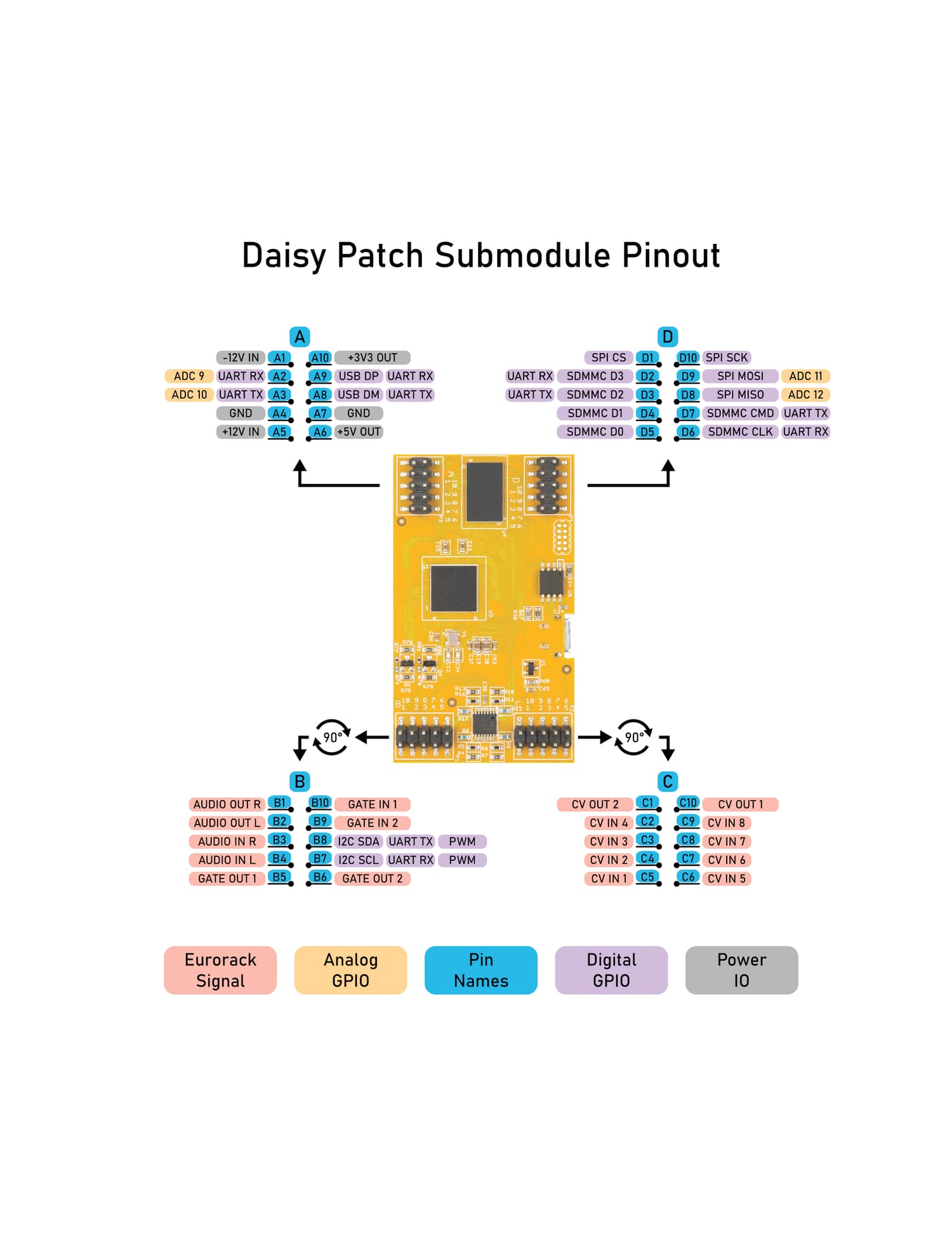
The Patch SM handles all of your signal conditioning for Eurorack modules so that you don’t actually need to implement any active circuitry.
It is the fastest way to get up and running in the Eurorack environment with Daisy.
So, just to make sure I understand correctly, all of the buffering and protection that you described earlier is already ‘baked in’ to the Patch SM? If so, that’s awesome…
Is it anything of a curveball if I’m planning on an application outside of the Eurorack world? Something standalone, desktop, or pedal-ish? Docs make it seem that power input could work with 9V?
Yes, that is correct! The CV ins/outs are already scaled according to the ranges mentioned in the datasheet and are completely protected against negative and/or excessive voltage.
The Patch SM is specifically designed for Eurorack signal levels including the power inputs of +/-12V.
If you’re interested in a desktop, or effects pedal application I would recommend checking out the Field and Petal hardware as jumping off points.
Me again, sorry. I’ve been chewing on the above advice and wondered if I could ask if all GPIO on the Seed are capable of PWM? E.g. could I use GPIO7-GPIO11 for that purpose?
Using Oopsy, will ‘cv out’ objects need any special treatment if not coming from a DAC pin?
Thank you, yes I’ve built the Terrarium and two of my own custom boards for pedals so far.
Since I’m hoping to add CV and MIDI connectivity for the next project, that’s where all my questions are coming from. Though the schematics from ES devices are very helpful, I still think there’s some core details about things like CV and PWM that I don’t quite grasp yet. Slow learner…
All GPIO pins on the daisy are capable of outputting software-generated PWM.
In oopsy, and libDaisy the LED component (used on the Pod, etc.) uses software PWM.
The Daisy Seed, and Patch SM both have some pins that are able to do hardware-generated PWM. Support for using this feature is currently being added to libDaisy, and will end up getting added to oopsy some time afterward.