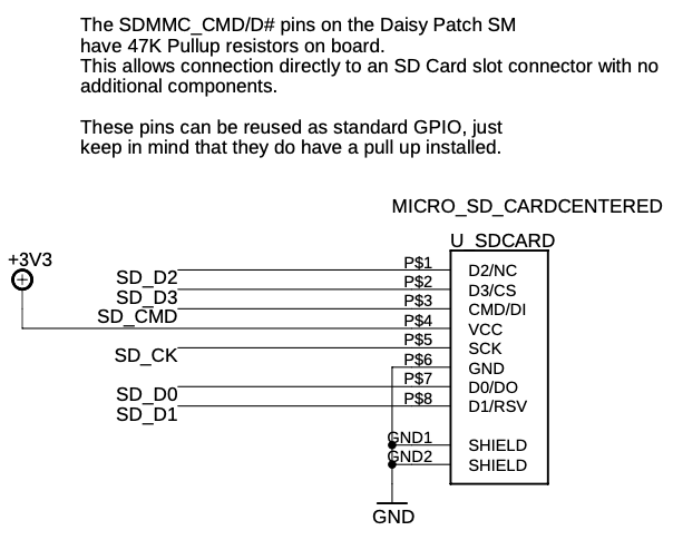
I would like to do some prototyping with an OLED attached to a patch.init(). I can get access to some of the needed pins directly from the carrier board but others are used for the Micro SD.
In the patch.init() design files schematic there is a statement close to the MICRO_SD that implies access to the GPIO pins via. the card slot.
“This allows connection directly to an SD Card slot connector with no additional components.”
How do I physically get access? I saw the “SparkFun microSD Sniffer”. Would that work? Are there other alternatives?
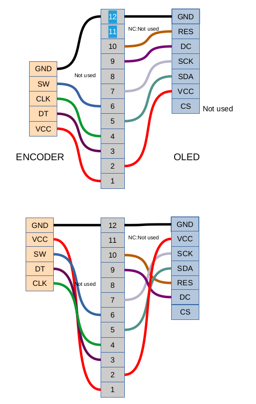
JMC64 on Discord was able to connect the Standard spi Oled 128x64 to patch.Init() and even have some pins left over for an encoder!
Here’s the diagram that was shared there by JMC64 (the bottom diagram is what it’ll “realistically” look like in terms of how the pins on the OLED are actually ordered. The top diagram was made to make it visually easier to follow).
Thank you very much! This is exactly what I was looking for. I guess my Discord search skills need some improvement. I also wasn’t aware that those pins where interchangeable. I need to learn more about GPIO, ect.
I am using the 128 * 64 SSD1306 like you and others have recommended.
@dreamer I did see that but I didn’t know I could use those pins for the SDA and DC. I’m just barely familiar with pin naming conventions. I used different pins when I tried it out on a bare patch_sm.