So I did end up figuring this out, but I don’t know how compatible the code will be with the daisy platform. What I mean by that is you may need to breakout CubeMX to generate the code, because they use a different chip than I do.
The way I went about it is by using a Timer in “Input Capture” mode. I believe this method is the most accurate way to detect the time elapsed between incoming pulses. It doesn’t use any CPU cycles to calculate the number of “ticks” between two rising edges on the gpio pin. This value is simply stored in a timer register and accessible when you need it via __HAL_TIM_GetCompare().
Now if you clock your timer directly from the system core clock, then that timer is going to increment its counter extremely fast, so fast that you will find the timer overflows before the next rising edge of the input occurs. Since we are generally trying to determine the time between quarter notes or 8th notes, the timer needs to be configured to sample the frequency of really slow signals. To do this I used an additional timer to “drive” the timer configured in input capture mode.
This was probably a poor explanation… but here are the CubeMX Config screenshots of my TIM1 and TIM2 configuration:
TIM1
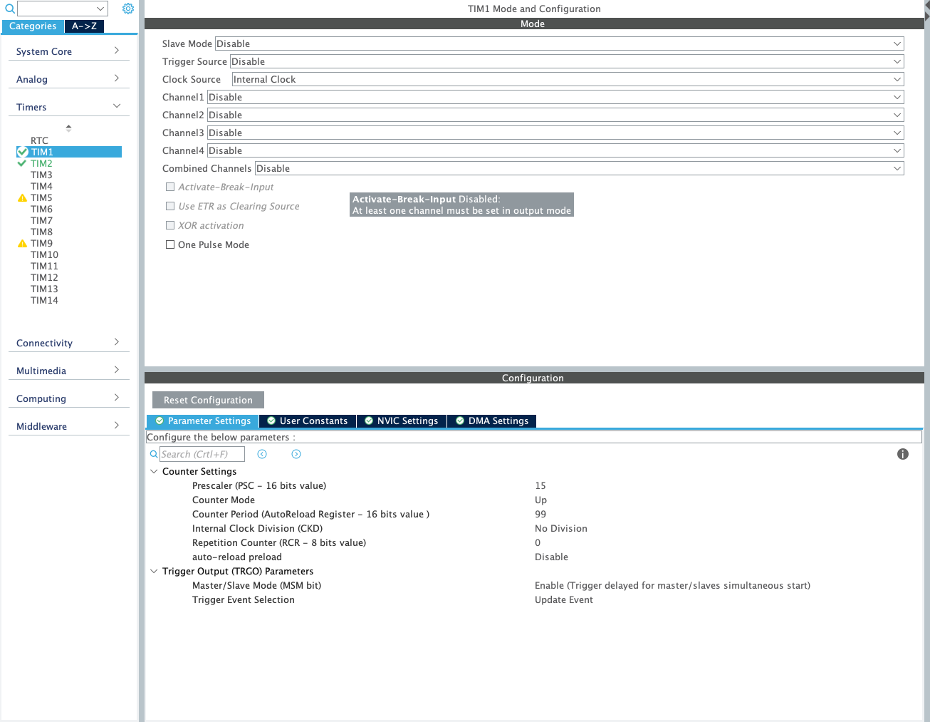
TIM2

To clarify, TIM1 is being use as the Master clock source for TIM2.
TIM2 is configured in “Input Capture Mode” which triggers an interrupt routine every time there is a rising edge on “Input Capture Channel 4” (which is just a GPIO).
The interrupt function looks like this:
void HAL_TIM_IC_CaptureCallback(TIM_HandleTypeDef *htim)
{
  if (htim->Instance == TIM2)
  {
    __HAL_TIM_SetCounter(&htim2, 0); // reset TIM2 counter after each input capture
    inputCapture = __HAL_TIM_GetCompare(&htim2, TIM_CHANNEL_4);
  }
}
This is really just the beginning of the battle though. After you get to this point you would then start adding code to that interupt routine which clocks your sequencer or do whatever your application needs to do with that inputCapture value.