Hello, sorry if this is a dumb question.
I’m trying to design the circuitry required to build a guitar pedal using the daisy seed to run the software we’ll write to complete DSP operations, but I’m having trouble trying to understand what other people have done in the past.
The Daisy Seed datasheet says that the absolute min/max voltage of the Audio_In pin is -1.8V/1.8V (3.6Vpp), however I’ve seen schematics of input circuitry that add voltage to the input of the op amp such as this:
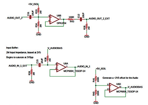
My question is why there is an audiobias/increase in voltage into the input circuit? I don’t see why we wouldn’t just try to achieve line level.
Any guidance on tis would be appreciated, thanks!