Heyyo! Noob question here. I am attempting to set up my daisy seed + a push button on a breadboard. I have the audio examples working, but I can’t get the DaisyDuino Button example to work.
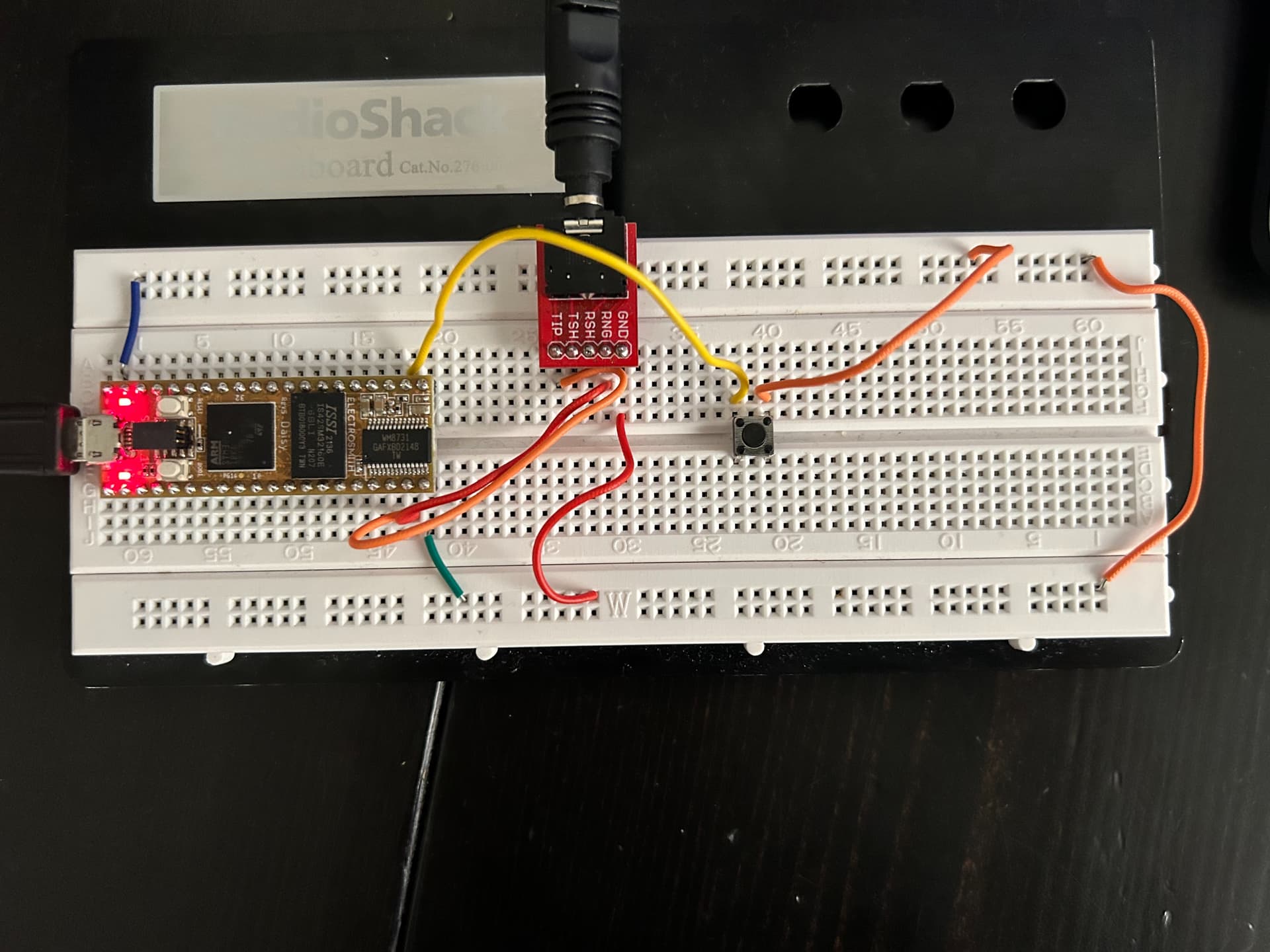
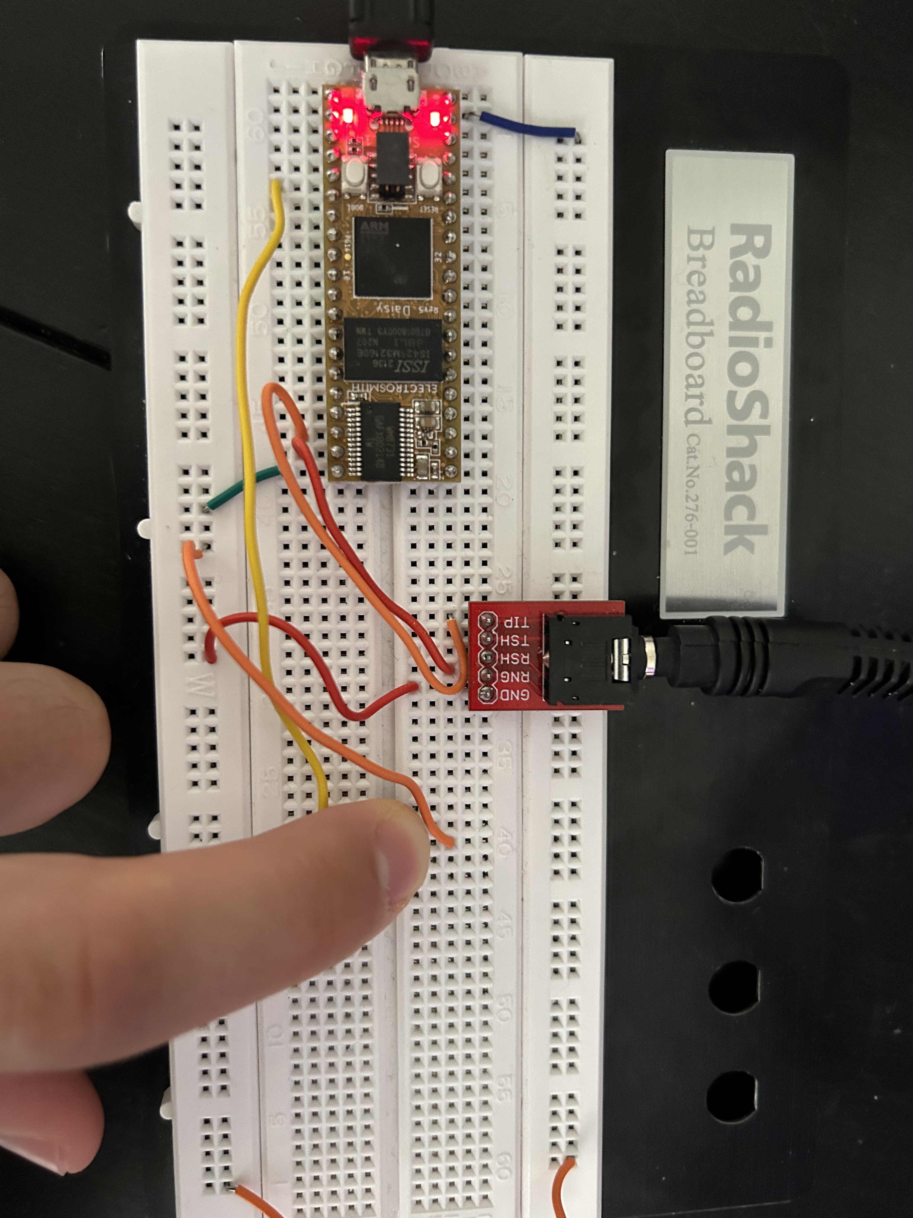
Here is a picture of my breadboard setup:
And here is my code:
// Title: Button
// Description: Turn an led on and off with a button
// Hardware: DaisyHardware
// Author: Ben Sergentanis
// Breadboard:
// https://raw.githubusercontent.com/electro-smith/DaisyExamples/master/seed/Button/resources/Button_bb.png
// Schematic:
// https://raw.githubusercontent.com/electro-smith/DaisyExamples/master/seed/Button/resources/Button_schem.png

#include "DaisyDuino.h"

Switch button;

void setup() {
  // setup the button
  // update at 1kHz, no invert, on pin 15
  button.Init(1000, true, 15, 2);

  pinMode(LED_BUILTIN, OUTPUT);
}
void loop() {
  // Debounce the button
  button.Debounce();

  // If the button is pressed, turn the LED on
  digitalWrite(LED_BUILTIN, button.Pressed());

  // wait 1 ms
  delay(1);
}
Nothing happens when I press the button. I cant get it to read through serial either. Please let me know if you can see what I am doing wrong. Thank you! 
Welcome Nightshifts!!
One thing I noticed is that you accidentally connected your blue wire to the VIN pin of the Daisy when you should be connected to the DGND pin.
Could you adjust and see if things are working now? Let me know, thanks!!
Hey @Takumi_Ogata, thanks so much for your response!
It was just a weird angle that the picture was taken, I believe its in the correctt DGND pin, still no luck.
Any other suggestions for how to set up and test the button?
Thanks,
Andrews
I just want to confirm that pressing the button doesn’t light up the onboard LED, correct?
It looks lit in that first photo, so I just wanted to check.
The code works fine so I’m guessing there is something with the circuit.
Here are my guesses.
- The breadboard’s rail is divided into two at the “W” point. So the AGND (green wire) may not actually be reaching the orange wire for example. It’s reaching the ground for the audio jack since it’s right before the possible split.
- Faulty wires
- Faulty component (specifically the switch)
Troubleshoot these and let me know if it helps!
Oh amazing! Thanks so much @Takumi_Ogata . It was the “W” point split. I connected everything to the left side of the board and it works. Very much appreciated.
1 Like
YES!!!
As your circuit becomes bigger and more complex, you can always bridge the two separate rails via wire.
Looking forward to seeing what you create!!
And always feel free to ask questions too.